EasyManua.ls Logo

I.C.E Iceball Pro - User Manual

I.C.E Iceball Pro
26 pages
Print Icon
To Next Page IconTo Next Page
Loading...
1
&
User Manual
Assembly Guide
Question and Answer IconNeed help?

Do you have a question about the I.C.E Iceball Pro and is the answer not in the manual?

Summary

Safety Before You Begin

AC Power Safety Precautions

Details on accessing the main fuse, its location, and specifications for 120V users.

Preparation for Assembly

Component Identification Guide

Lists and illustrates all parts and hardware included for assembly.

Essential Tools and Accessories

Identifies necessary tools like Allen wrenches and specific components such as latch tools.

Cabinet Structure Overview

Illustrates the main back cabinet and side panels of the game.

Customer Service Contact

Provides contact details for missing parts or service inquiries.

Assembly Step 1: Initial Setup

Cabinet Protection Method

Recommends using protective foam from packaging to prevent cabinet damage during assembly.

Wire Harness Routing

Ensures wire harness is tucked safely in the channel before inserting the side panel.

Assembly Step 2: Connecting Main Sections

Aligning Cabinet Panels

Suggests pushing the ramp down to ensure the side panel aligns flush with the ramp assembly.

Assembly Step 3: Securing Ramp Assembly

Ramp Attachment Hardware

Specific instruction for securing the ramp using Allen bolts and fender washers.

Assembly Step 4 & 5: Wiring and Latches

RGB Harness Connection Point

Instruction to connect the RGB harness originating from the support bar.

Cabinet Latch Preparation

Guides on partially extending latches using the latch tool for easier cabinet joining.

Assembly Step 6: Securing Side Panels

Attaching Clear Side Panels

Details using bolts, washers, and connectors to secure the clear plastic side panels.

Bottom Component Installation

Instruction for installing the bottom panel with bumper and joint connector.

Assembly Step 7: Joining Cabinet Halves

Final Latch Engagement

Emphasizes locking the latches securely before inserting the latch plugs.

Assembly Step 8: Internal Connections

Connecting Internal Wiring Harnesses

Instruction to connect various internal wiring harnesses at the sides and underneath.

Assembly Step 9: Power Up Procedure

Grounding Outlet Safety Mandate

Critical safety instruction mandating the use of a grounded AC outlet for operation.

Third Prong Adapter Prohibition

Warning against using adapters that eliminate or bypass the essential third prong ground connection.

Cabinet Lock Operation

Guides on using keys to unlock the main cabinet locks by turning clockwise.

Activating the Game Power

Instructions on flipping the AC power switch to the 'on' position, indicated by an 'I'.

Understanding Game Modes

Arcade Game Mode Details

Describes the classic alley roller game where players aim for maximum points.

First to Zero Game Objective

Explains the goal of reaching zero points first by subtracting points with each ball.

Fast N Accurate Gameplay

Details the fast-paced mode focusing on accuracy and speed for bonus points.

Cricket Game Rules

Describes the dartboard-inspired game where hitting holes three times is key.

Combo Bonus Multiplier Explained

Explains the bonus multiplier awarded for hitting the same hole consecutively.

In-Game Volume Adjustment

Provides instructions on how to adjust game volume during play using arrow keys.

Troubleshooting Doorway Fitment

Cabinet Disassembly Guide

Steps to take the back cabinet apart if it doesn't fit through a doorway.

Latch Hole Plug Removal Technique

Instruction to remove latch hole plugs using a small flat blade screwdriver.

Unlocking Cabinet Latches

Guidance on using the latch tool to unlock the four cabinet latches.

Customizing Game Settings

Arcade Mode Configuration

Details accent color settings and high score reset options for Arcade mode.

First to Zero Mode Settings

Lists starting points, high score reset, and default configuration for First to Zero.

Fast N Accurate Mode Options

Outlines high score reset and default settings for the Fast N Accurate mode.

Cricket Mode Configuration

Covers ball count per round, high score reset, and default settings for Cricket.

Combo Bonus Mode Settings

Details ball count per game, high score reset, and default settings for Combo Bonus.

Diagnostic Procedures for Repair

Entering Diagnostic Mode

Explains how to enter the diagnostic mode by pressing and holding the Down arrow button.

Interpreting Diagnostic Output

Describes how the diagnostic mode displays faults and the status of buttons and sensors.

Score Sensor Testing Method

Details the procedure for testing score sensors by dropping balls into holes.

Accessing Game Score Sensors

Playfield Removal for Sensor Access

Instructions on removing bolts and lifting out the playfield to access score sensors.

Visual Identification of Score Sensors

Identifies the physical location of the score sensors within the game's playfield area.

Score Sensor Replacement Guide

Safety Warning: Disconnect Power

Critical safety warning to disconnect the AC power cord before replacing any sensors.

10, 20, 30, 40 Point Sensor Details

Details the score sensors for 10, 20, 30, and 40 point holes and their board configuration.

100 Point Score Sensor Replacement

Safety Warning: Power Disconnection

Reiterates the safety instruction to unplug the AC power cord before sensor replacement.

Left and Right 100 Point Sensor Specs

Describes the left and right 100 point score sensors and their alignment across the playfield.

Accessing Internal Electronics

Display Assembly Access

Instructions on using keys to unlock and lower the display assembly for access.

Key Electronic Component Locations

Identifies and labels the AC Fuse, +5 Power, Mainboard, and +12 Power units.

Replacing AC Fuse and Electronics

AC Fuse Removal and Installation

Step-by-step guide on how to safely remove and install the AC fuse.

110 V Version Fuse Information

Specifics on the single fuse location and rating for 110V models.

Electronics Panel Access Procedure

Instructions for removing mounting screws to pull out the electronics panel for maintenance.

Power Cord Safety for Maintenance

Emphasizes ensuring the AC power cord is unplugged before performing any electronics maintenance.

Power Supply Unit Replacement

Replacing the +5 V Power Supply

Steps for replacing the +5V power supply, including wire color identification for connections.

Replacing the +12 V Power Supply

Steps for replacing the +12V power supply, including wire color identification for connections.

Power Supply Replacement Safety

Crucial safety reminder to ensure the AC power cord is unplugged before replacing power supplies.

Main Board and SD Card Management

Main Board Replacement Process

Instructions using a nut driver to remove and replace the main circuit board.

SD Card Insertion and Removal

Procedure for inserting and removing the SD card from its socket on the board.

LED Power Fuse Specifications

Overhead LED Fuse Rating

Specifies the 4 AMP @ 250 volt FAST-BLOW fuse for overhead RGB LEDs.

Under Cabinet LED Fuse Rating

Specifies the 5 AMP @ 250 volt FAST-BLOW fuse for under cabinet RGB LEDs.

Main Board Connector Pinouts

Audio, Buttons, and Power Connections

Details pinouts and wire colors for audio, button, and power input headers.

Output and RGB Lighting Connections

Describes pinouts for +5VDC output and RGB lighting interface headers.

Sensor and Display Interface

Details pinouts and wire colors for sensor and display interface headers.

ICE Ball Pro Warranty Information

Warranty Period and Coverage

States the one-year warranty period for defects in materials and workmanship from purchase date.

Conditions for Warranty Exclusion

Lists specific conditions under which warranty claims may be denied by I.C.E. Inc.

RMA Requirement for Service

Explains the mandatory process of obtaining an authorized RMA number for warranty service.

Company Contact and Location

Provides company contact details and address for Innovative Concepts in Entertainment.

Overview

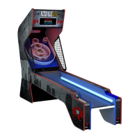
The device described in the manual is the ICEBALL Pro Home Edition arcade game, a classic alley roller game designed for indoor use.

Function Description

The ICEBALL Pro is an arcade game where players roll balls into scoring holes to accumulate points. It offers multiple game modes, including:

  • ARCADE: The classic alley roller game where players throw 9 balls to achieve the highest score.
  • FIRST TO ZERO: Players compete to reach a score of zero exactly by subtracting points with each ball thrown.
  • FAST N ACCURATE: Focuses on speed and accuracy to score points, with a "Time Bonus" for hitting the same hole quickly and precisely.
  • CRICKET: A dartboard-inspired game where players hit each hole three times, with the winner being the one who uses the fewest balls.
  • COMBO BONUS: Rewards accuracy by giving a 3x bonus multiplier for hitting the same hole three times in a row.

The game features a glowing cabinet and an upper display. Players can select from five game modes and up to four players. Game volume can be adjusted using arrow keys during gameplay.

Important Technical Specifications

  • Footprint: 120" (length) x 30" (width) x 84" (height).
  • Power Supply: The game uses a grounded A.C. receptacle. The power supply is not voltage adjustable.
  • Main Fuse (120V version): 3 AMPS at 250Volt, slow blow type. It is accessed through the top front of the game.
  • LED +12 VDC Power Fuses:
    • Left Fuse: 4 AMP @ 250 volt FAST-BLOW, protects Overhead RGB LED's.
    • Right Fuse: 5 AMP @ 250 volt FAST-BLOW, protects Under Cabinet RGB LED's.
  • Balls: Comes with 9 balls (color may vary).
  • Assembly: Requires at least two adults for assembly. The back cabinet can be disassembled for easier transport through doorways.
  • Electronics: Includes a main board, +5V supply, and +12V supply. The main board uses an SDCARD for game files.
  • Sensors: Features multiple score sensors (10, 20, 30, 40, and left/right 100 points) and buttons (player, game, up, down, start).

Usage Features

  • Game Start: Press the "START" button to power on the game.
  • Game Selection: Use the "GAME" button to cycle through available games.
  • Player Selection: Use the "PLAYER" button to select the number of players.
  • Volume Adjustment: Use the arrow keys during gameplay.
  • Game Options: Accessible by pressing the left and right arrow buttons simultaneously in standby mode. Options include accent LED colors (for the cabinet, affecting all games), starting points for "First to Zero," number of balls per round for "Cricket," number of balls per game for "Combo Bonus," high score reset, and game revision display.
  • Diagnostic Mode: Activated by pressing and holding the Down arrow button in standby mode. This mode helps identify faults by displaying bad files on the SDCARD and testing button presses and score sensors. It lights up a letter or number red when a button is pressed or a ball is detected in a score hole.

Maintenance Features

  • AC Power Information: The main fuse is located behind a small panel above the power cord.
  • Accessing Electronics: The display assembly hinges down after unlocking two top locks with keys, providing access to the AC fuse, +5V supply, +12V supply, and main board.
  • Replacing AC Fuse: Requires a small flat blade screwdriver to pry open the lid and remove the red fuse holder.
  • Replacing Electronics (General): Requires unplugging the AC cord. The electronics panel can be pulled out by removing two mounting thumb screws.
  • Replacing +5V Supply: Involves removing two mounting bolts and loosening wire terminals with a #2 Phillips screwdriver.
  • Replacing +12V Supply: Involves removing two mounting bolts and loosening wire terminals.
  • Replacing Main Board: Requires a 1/4" nut driver to remove four plastic standoffs. Replacing the main board will reset all settings to default.
  • Replacing SDCARD: The SDCARD is located in a socket on top of the main board. Pushing the card in will cause it to pop out for removal; pushing a replacement card in will click and lock it.
  • Accessing Score Sensors: Involves removing two bolts with a 5/32 Allen wrench and lifting the playfield out of the game.
  • Replacing Score Sensors: Each sensor consists of two boards connected by a harness. One board is held by a #2 Phillips screw, and the other by a standoff. The smaller board is inserted through bottom cabinet holes and attached to the opposite side. Crucially, the AC cord must be unplugged before replacing any sensors or electronics.
  • Warranty: I.C.E. Inc provides a ONE YEAR warranty from the purchase date for defects in materials and workmanship for the ICEBALL Pro Home Edition. Warranty claims require an authorized RMA #, game serial #, original invoice #, and a detailed description of the fault. The warranty does not cover commercial operation, unwarranted stress/abuse, neglect, or damage from arbitrary repair/modification.

I.C.E Iceball Pro Specifications

General IconGeneral
BrandI.C.E
ModelIceball Pro
CategoryArcade Game Machines
LanguageEnglish

Related product manuals