EasyManuals Logo

IAI RCM-GW-CC User Manual

IAI RCM-GW-CC
132 pages
To Next Page IconTo Next Page
To Previous Page IconTo Previous Page
Page #114 background imageLoading...
Page #114 background image
110
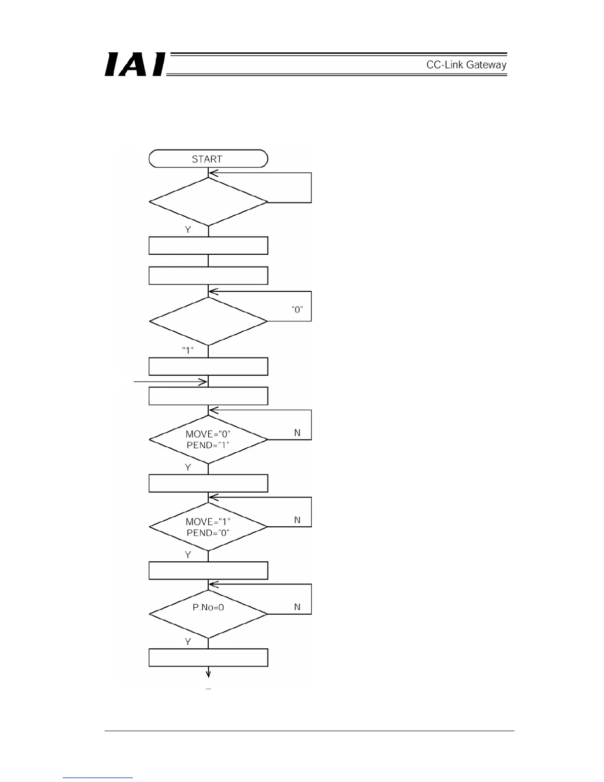
9.7 Ladder Sequence Flowchart
Operation flowchart for the second axis (axis 0) and third axis (axis 1) which are DeviceNet slave axes is as
follows. Insides of parentheses are SIO link axis Nos.
Gateway unit
normal
SIO link axis designation
SIO link start
Axes (0)(1) PWR
check
Turn on servo for axes (0)(1)
Command P.No.=0 to axes (0)(1)
Set CSTR to “1”
Set CSTR to “0”
One second timer
Positioning completed
[
2
]
[
1
]

Questions and Answers:

Question and Answer IconNeed help?

Do you have a question about the IAI RCM-GW-CC and is the answer not in the manual?

IAI RCM-GW-CC Specifications

General IconGeneral
BrandIAI
ModelRCM-GW-CC
CategoryGateway
LanguageEnglish

Related product manuals