75
7. Contents of communication signal
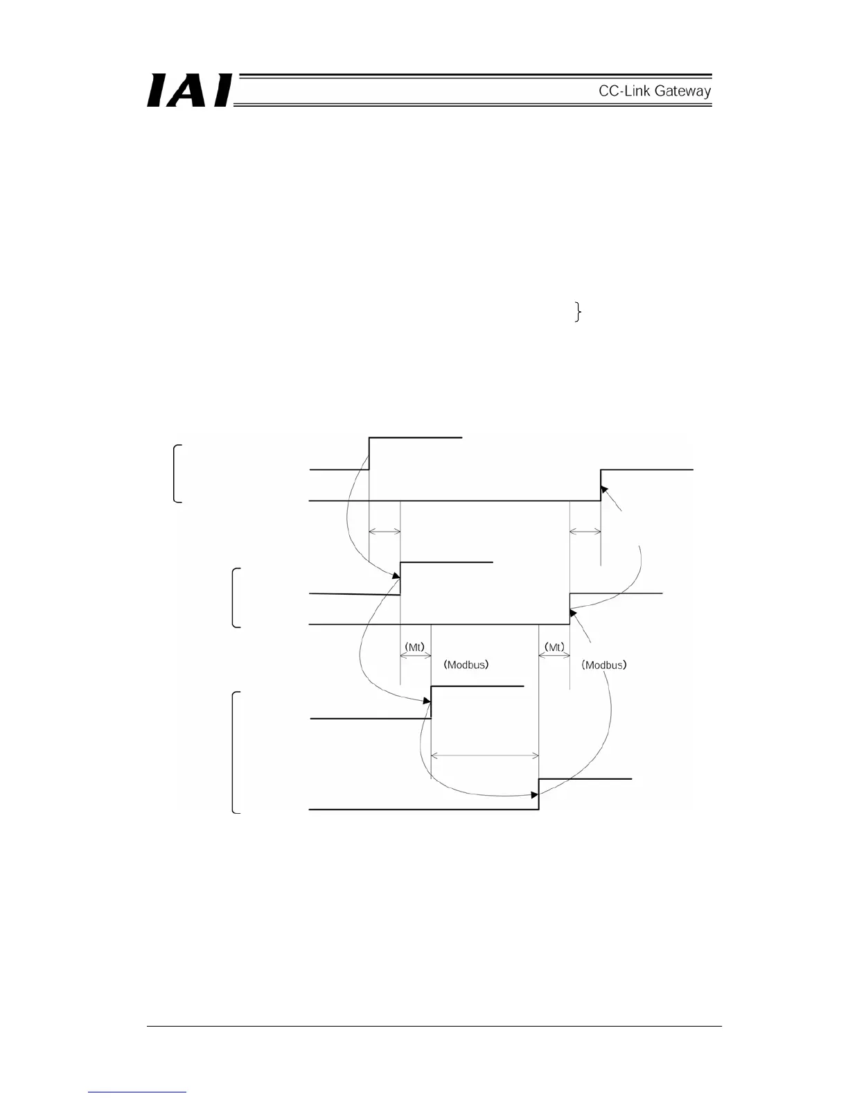
7.1 Outline of timing for communication signal
In order to operate robo-cylinder by the sequence program for the PLC, any of the control signals is turned ON,
and maximum response time until the response (status) returns to the PLC is expressed by the following
equation.
Maximum response time (msec) = Yt + Xt + 2 × Mt + Command processing time (such as operating time)
Mt = 10(msec) × (n + 1) : SIO link (Modbus) Cycle time
n : Number of controlled axes
Yt : Master station → Remote I/O station transmission delay time
Xt : Remote I/O station → Master station transmission delay time
For Master station → Remote I/O station transmission delay time (Yt), Remote I/O station → Master
station transmission delay time, refer to the Operation Manuals for the CC-Link master unit and PLC to be
mounted.
(Note) When communication error is caused due to a problem on the transmission path, communication
retry (retry times = 3) occurs and a longer SIO link cycle time (Mt) than normal may occur.
CC-Link transmission
delay time
PLC sequence program
Control signal
Status signal
Gateway
Control signal
Status signal
Controler
Control signal
Status signal
Master station → Remote I/O
station
Transmission delay time (Yt)
Remote I/O station→ Master
station
Transmission delay time (Xt)
SIO link cycle time
SIO link cycle time
Command
processing time
 Loading...