9
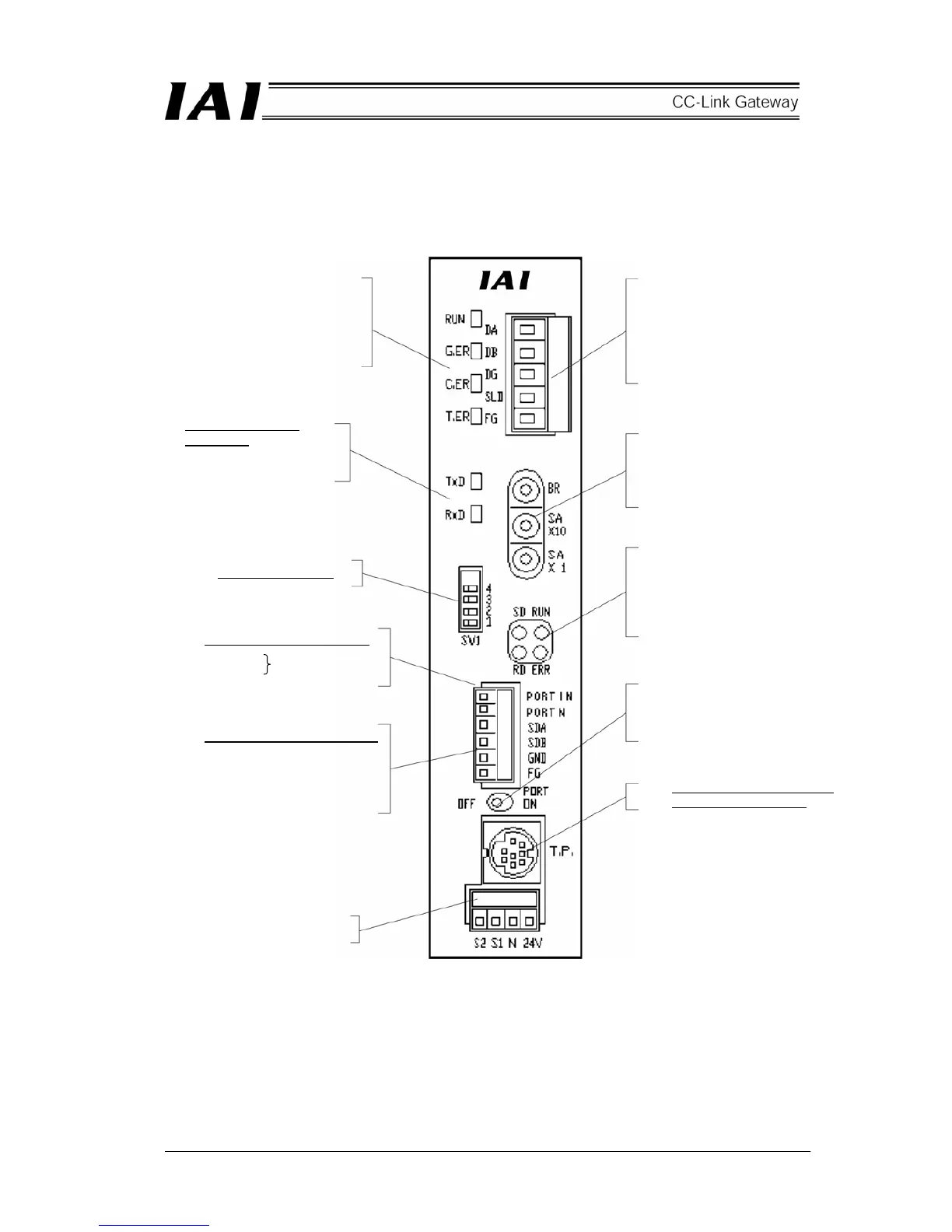
2.3 Name and function of each part
[1] Gateway status
indication LED
RUN: Normal
G.ER: Error
C.ER: CC-Link error
T.ER: SIO link error
[2] SIO communication
status LED
TxD: Data transmission
RxD: Data reception
[3] Mode setting switch
[SIO communication connector]
[4] External port switching input
PORT IN
PORT N
Port switching
[5] Controller communication line
SDA: Communication line
SDB: Communication line
GND: Ground
FG: Frame ground
[11] Power supply input connector
[6] CC-Link communication
connector
DA: Communication line
DB: Communication line
DG: Ground
SLD: Shield
FG: Earth
[7] CC-Link setting switch
BR: Baud rate
SA × 10 and Sa × 1:
Station No. (Decimal,
2 digits)
[8] CC-Link communication
status LED
SD: Data communication
RD: Data reception
RUN: Normal
ERR: Error
[9] Port switch
ON: Port on
OFF: Port off
[10] Connector for teaching box
and personal computer
 Loading...