19
Reference Outline of CC-Link network configuration
For details of the CC-Link, refer to the Operation Manual for the master side (PLC). This section
describes a point for network wiring.
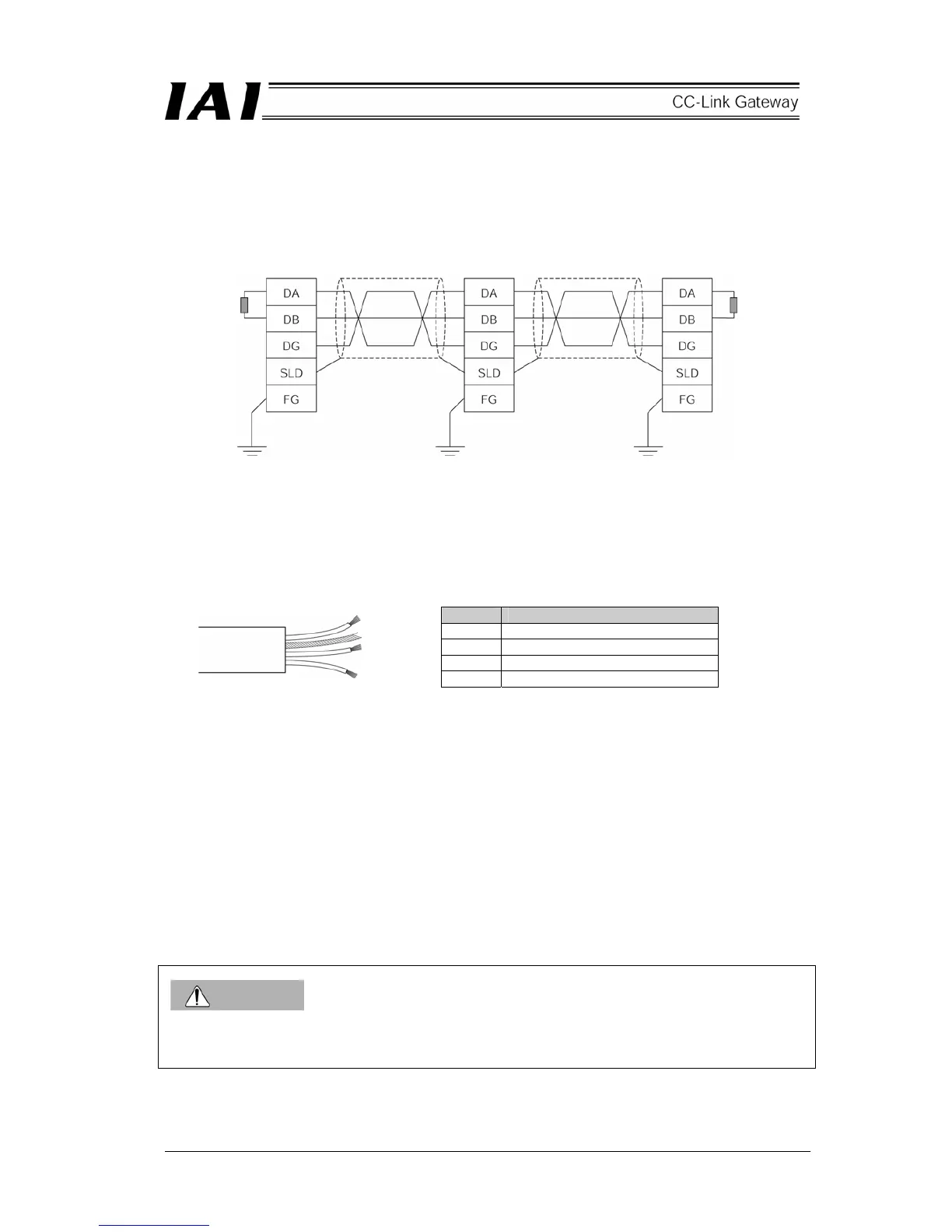
The following diagram shows an example of network connection.
(1) Equipment connected by the CC-Link is referred to as a station, and 0 to 64 can be set as a station No.
The master station and slave station can be placed on any position.
(2) Connection is made by a multi-drop method directly branching at each station, and a T-branch using
commercially available terminal block, etc., is allowed.
(3) Use a dedicated shielded 3-core twisted paired cable as a cable.
The dedicated cable is as follows.
Color Signal type
Blue Communication line A (DA)
White Communication line B (DB)
Yellow Communication ground line (DG)
- Shield (SLD)
(4) It is necessary to install terminal resistors on both ends of the CC-Link system. The terminal resistor is
connected between “DA” and “DB,” however, it differs with the cable being used.
(5) Communication rate is restricted by network length (total branch length, network maximum length).
CAUTION
Set the GND (ground) level of the power supply for each controller connected to the gateway to the power
supply for the gateway.
Master station Slave station Slave station
Terminal resistor
(Blue)
(White)
(Yellow)
Terminal resistor
CC-Link dedicated
cable
CC-Link dedicated
cable
 Loading...