41
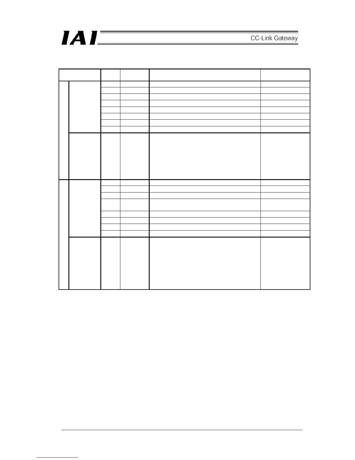
Details of input and output signal
Signal type Bit
Signal
name
Contents Detail
F/7 - Cannot be used. -
E/6 - Cannot be used. -
D/5 - Cannot be used. -
C/4 SON Servo on command
B/3 STP Pause command
A/2 HOME Home return command
9/1 CSTR Start command
Control
signal
8/0 RES Reset command
PLC output
Position
data
designation
16 bit
data
-
16 bit integer with sign (unit: 0.01mm)
Set position data in hexadecimal number.
Example) The signal becomes 09EC
H
(decimal
2540) in the case of +25.4.
(Note)
● When the integer is negative, it is indicated
by complement of 2, therefore, the
uppermost bit becomes “1.”
F/7 EMGS On emergency stop
E/6 - Cannot be used. -
D/5 PWR Controller preparation completion
C/4 SV
Operation preparation completion (Servo on
status)
B/3 MOVE On moving
A/2 HEND Home return completion
9/1 PEND Positioning completion
Status
signal
8/0 ALM Alarm occurring
PLC input
Present
position
data
16 bit
data
-
16 bit integer with sign (unit: 0.01mm)
Present position data is outputted in
hexadecimal number.
Example) 09EC
H
(decimal 2540) is outputted in
the case of +25.4.
(Note)
● When the integer is negative, it is indicated
by complement of 2, therefore, the
uppermost bit becomes “1.”
 Loading...