48
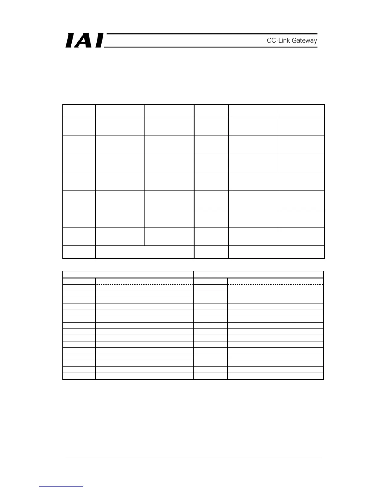
(1) Address configuration
In this mode, input and output for gateway control signal consist of two words respectively, and control
signal for each signal consists of one word respectively for input and output bit register and two words
respectively for input and output word register.
Numeric values in the parentheses represent axis Nos.
PLC output⇒Gateway unit⇒Each axis input Each axis output⇒Gateway unit⇒PLC input
Output
register
bF
Higher byte
b8
b7
Lower byte
b0
Input
register
bF
Higher byte
b8
b7
Lower byte
b0
RY 0F – 00 Acceleration and
deceleration
designation (1)
Control signal (0) RX 0F – 00
Cannot be used Status signal (0)
RY 1F – 10 Acceleration and
deceleration
designation (3)
Control signal (2) RX 1F – 10
Cannot be used Status signal (1)
RY 2F – 20 Acceleration and
deceleration
designation (5)
Control signal (4) RX 2F – 20
Cannot be used Status signal (2)
RY 3F – 30
Acceleration and
deceleration
designation (7)
Control signal (6)
RX 3F – 30 Cannot be used Status signal (3)
RY 4F – 40
Acceleration and
deceleration
designation (9)
Control signal (8)
RX 4F – 40 Cannot be used Status signal (4)
RY 5F – 50
Acceleration and
deceleration
designation (11)
Control signal (10)
RX 5F – 50 Cannot be used Status signal (5)
RY 6F – 60
Acceleration and
deceleration
designation (13)
Control signal (12)
RX 6F – 60 Cannot be used Status signal (6)
RY 7F – 70
Prohibited from use because this is in
CC-Link system region
RX 7F – 70
Prohibited from use because this is in
CC-Link system region
Output (writing) Register=Word register Input (writing) Register=Word register
RWw 0 Gateway control signal 0 RWr 0 Gateway status signal 0
RWw 1 Gateway control signal 1 RWr 1 Gateway status signal 1
RWw 2 Speed designation (0) RWr 2 Cannot be used
RWw 3 Position data designation (0) RWr 3 Present position data (0)
RWw 4 Speed designation (1) RWr 4 Cannot be used
RWw 5 Position data designation (1) RWr 5 Present position data (1)
RWw 6 Speed designation (2) RWr 6 Cannot be used
RWw 7 Position data designation (2) RWr 7 Present position data (2)
RWw 8 Speed designation (3) RWr 8 Cannot be used
RWw 9 Position data designation (3) RWr 9 Present position data (3)
RWw A Speed designation (4) RWr A Cannot be used
RWw B Position data designation (4) RWr B Present position data (4)
RWw C Speed designation (5) RWr C Cannot be used
RWw D Position data designation (5) RWr D Present position data (5)
RWw E Speed designation (6) RWr E Cannot be used
RWw F Position data designation (6) RWr F Present position data (6)
 Loading...