1-13
INSTALLATION
SL 80-399 MODULATING GAS BOILER
SL 26-260 G3, SL 40-399 G3 MODULATING GAS BOILERS
d) Sidewall Direct Vent with Stainless Sidewall Terminal shall be terminated as follows:
• The Stainless Sidewall Terminal (SST) 3 inch IBC part number 180-149 (sold
separately included with the IBC kit P-257 ), is the only direct vent sidewall terminal
approved for use with the IBC boiler model.
• The boiler’s controller is required to be the Touchscreen type and have software
version 1.02.2 or later installed for SST to be used.
• The SST shall be installed in compliance with the minimum vent clearances listed in a)
above.
• The installation instructions included with the kit shall be carefully followed.
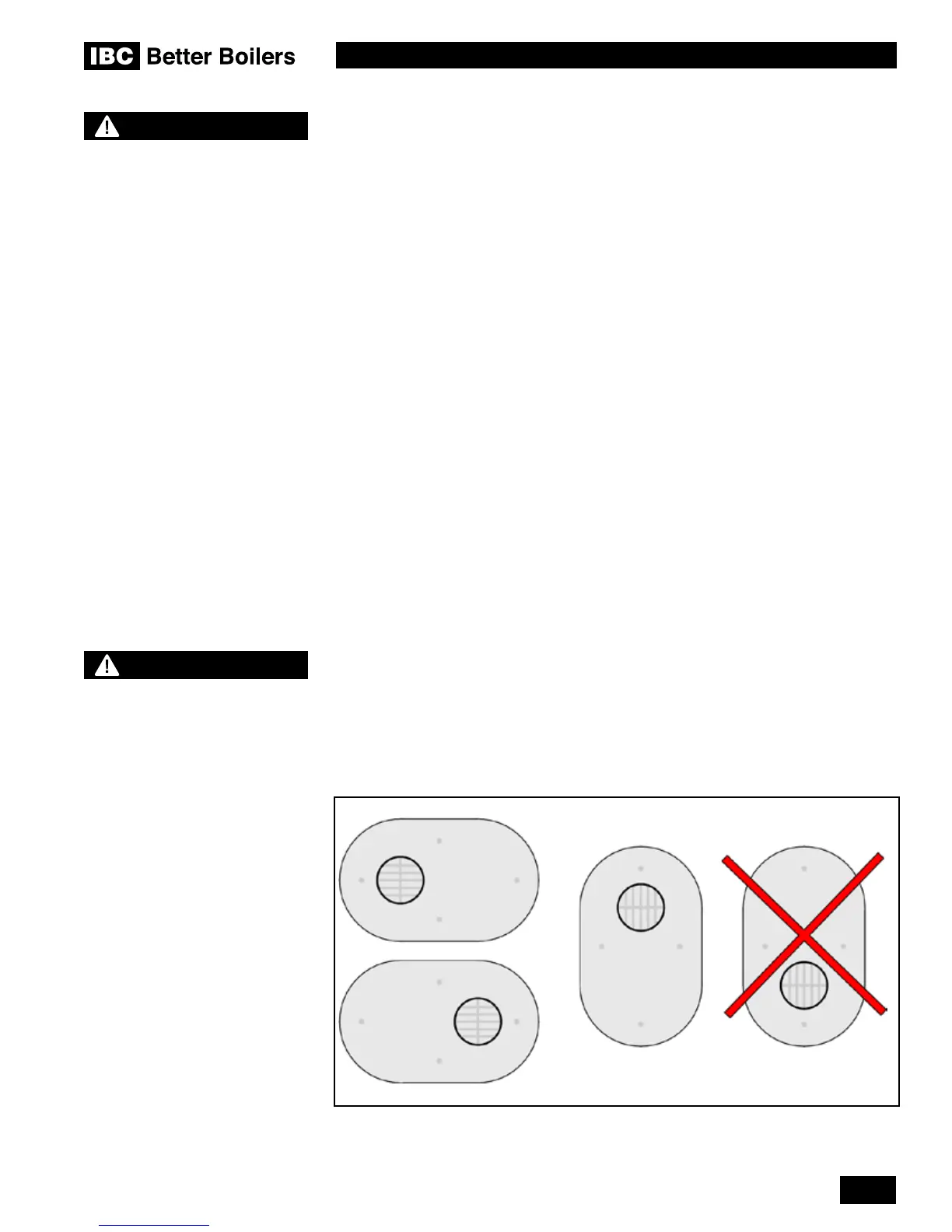
• The SST shall only be installed with the vent and intake pipes horizontally beside
each other or vertically with the vent pipe on top as shown in Figure 14. The vent pipe
cannot be installed below the intake. The vent cap must be installed with the openings
directed up and down, as shown in Figure 14, and not side to side.
• The SST vent/air connections t Sched. 40 three inch PVC/CPVC pipe. PPs pipe
cannot be used with the SST. The pipes must extend completely through the wall as
shown in Figure 15 and immediately inside the wall adapt up to a 4 inch pipe using
a standard reducing coupling tting. Do not use a bushing. The SST is an external
xture, and is not part of the sealed vent system that runs inside the building.
• Ensure that the vent termination location does not exceed the allowed maximum
equivalent vent length, including the allowance for the SST, dened in this document
section 1.4.3 Vent Travel and section 1.4.7 “Direct Vent” Combustion Air Intake Piping.
• Multiple vent SST installations must be installed level with one another, and maintain
at least the minimum separation distances shown in Figures 16 and 17. The Terminals
shall not be stacked vertically.
•
The two basic methods for supplying combustion air to an IBC boiler are described in
sections 1.4.7 and 1.4.8.
e) Approved PVC Side Wall Termination kits are listed below:
• Ipex # 196984 2"
• Ipex # 196985 3"
• Ipex # 196986 4"
These kits are sold separately through the manufacturer.
WARNING
In areas of high snowfall, users
must be advised to check
side wall vent and air intake
terminations on a regular basis
to ensure blockage does not
occur.
Ipex # 196984 2" PVC, #196985 3" PVC, and # 196986 4" PVC
CAUTION
Take care installing Concentric
Side Wall Termination kits.
Blockage of the combustion
air intake can occur when the
outdoor temperature drops below
5°F/-15°C.

 Loading...


