INSTALLATION AND OPERATION INSTRUCTIONS
1-18
SL 80-399 MODULATING GAS BOILER
SL 26-260 G3, SL 40-399 G3 MODULATING GAS BOILERS
1.5 CONDENSATE REMOVAL
IBC’s specied vent conguration promotes the safe drainage of moisture from the boiler
and exhaust venting without owing liquids back through the heat exchanger (as done by
some other condensing boilers).
Reliable system operation requires (1) proper design and installation of exhaust venting
to allow condensate to run back to the drain/trap; (2) acid neutralization as appropriate. To
achieve these:
• Allow for a 1/4” per foot slope back to the vent connection, with appropriate hangers
to maintain that gradient.
• Ensure the supplied trap is correctly installed and lled with water.
• When required, add (and maintain in good condition) a neutralization tank.
1.5.1 Condensate Trap
The condensate trap must be installed on the drain connection at the base of the boiler as
shown in Figure 22.
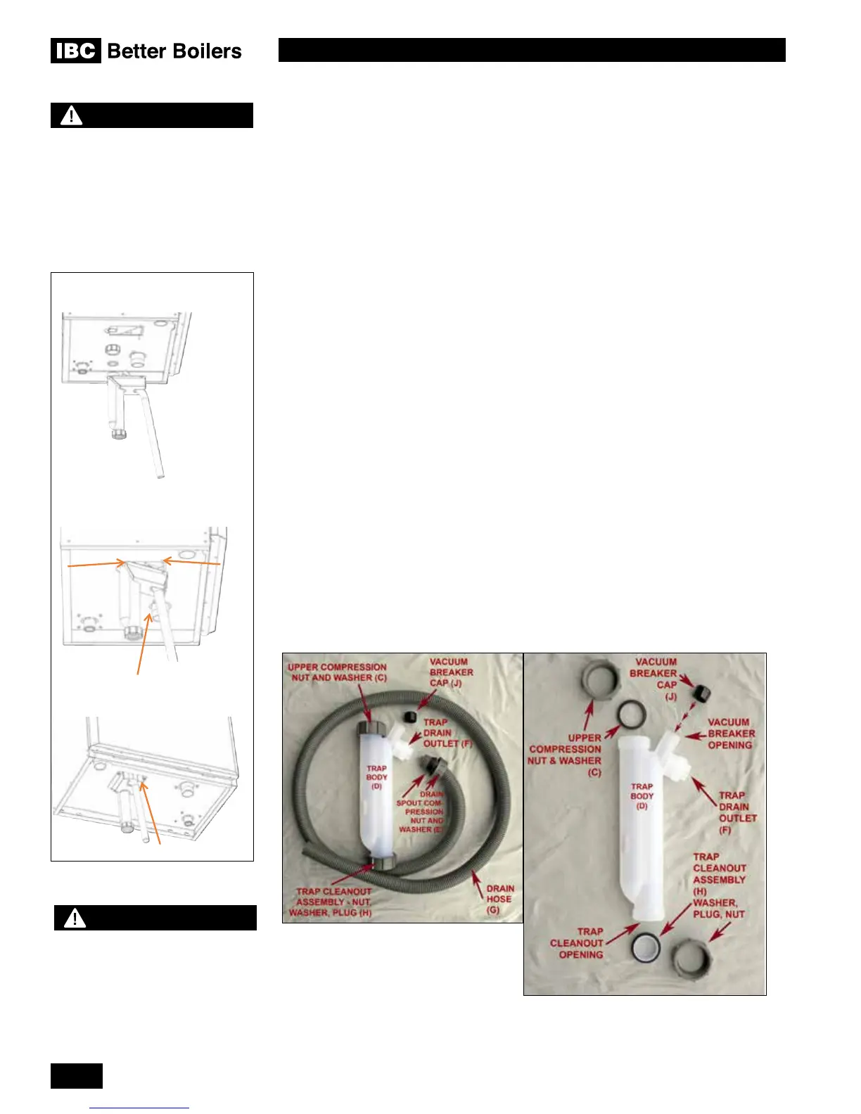
1.5.2 Condensate Trap Assembly - Installation
1. Remove the boiler door and remove the condensate trap door by removing the 2 nuts
and washers, lower the front of the trap door and slide forward. Undo the Drain Spout
Compression Nut (E), remove the Drain Hose (G) from Trap Drain Outlet (F). Place
the Vacuum breaker cap (J) over the Vacuum breaker opening and push rmly home.
Remove the Upper Compression Nut and Washer (C) and slide over the Boiler Drain
Outlet (A).
2. Fill the trap with water and slide
the trap body (D) over the Boiler Drain Outlet (A) and tighten.
Attach the Drain Hose (G) and tighten the Drain Spout Compression Nut (E).
3. Install the Condensate Trap Door and tighten the 2 hex screws. Check for leaks.
Condensate Trap, as shipped and
disassembled
WARNING
The Trap Door must be installed
as instructed and all trap ttings
must be tightened as instructed
to prevent leakage of ue gasses.
Failure to comply may result in
severe personal injury or death.
Figure 22: Condensate trap installation
WARNING
Fill trap with water before boiler
is rst red to prevent exhaust
fumes from entering room. Never
operate the boiler unless the trap
is lled with water.
Failure to comply will result in
severe personal injury or death.
trap and tube.
2. Slide retainer around trap and
slide retainer tabs into cabinet.
3. Pass tube through retainer.
4. Secure trap with nut and
washer.

 Loading...


