INSTALLATION AND OPERATION INSTRUCTIONS
1-28
SL 80-399 MODULATING GAS BOILER
SL 26-260 G3, SL 40-399 G3 MODULATING GAS BOILERS
1.7 GAS PIPING
The boilers require an inlet gas supply pressure of at least 4.0" w.c. for natural gas or
propane during high re operation. This will ensure that gas pressure measured at the gas
valve inlet pressure tap does not droop below 3.5" w.c. at high re. For either fuel, the inlet
pressure shall be no greater than 14.0" w.c. Conrm this pressure range is available with
your local gas supplier.
The inlet gas connection to the boiler is 3/4" NPT (female).
Adequate gas supply piping shall be provided with no smaller than 3/4" Sched 40 (e.g.
Iron Pipe Size (IPS)) and using a 1" w.c. pressure drop, in accordance with the following
chart:
MODEL
3/4"
IPS
1" IPS 1 1/4" IPS 1 1/2" IPS
SL 26-260 G3 (Natural Gas) 20' 80' 300' 600'
SL 26-260 G3 (Propane) 70' 200' 800' 1600'
SL 40-399 G3 (Natural Gas) 10' 40' 150' 300'
SL 40-399 G3 (Propane) 30' 100' 400' 900'
Table 6: Maximum Pipe Length (ft)
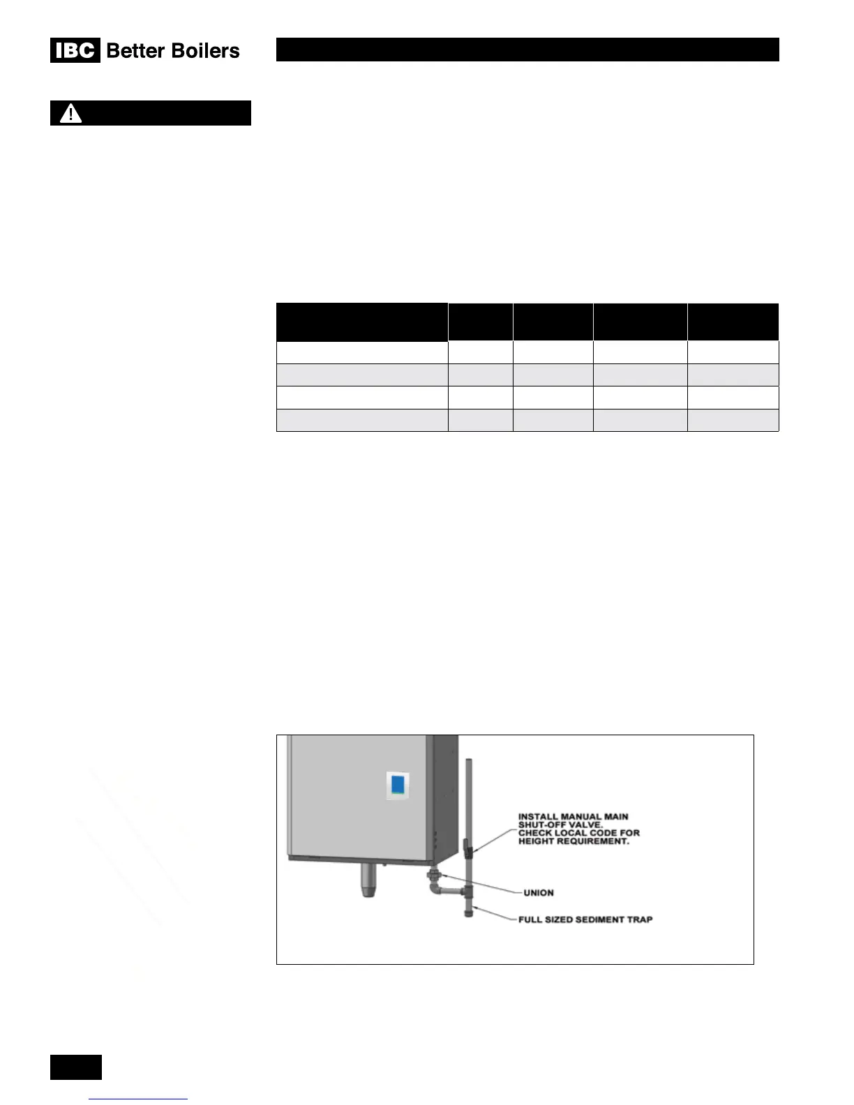
Gas piping must have a sediment trap ahead of the boiler’s gas valve (see Figure 34). A
manual shutoff valve must be located outside the boiler, in accordance with local codes/
standards. All threaded joints in gas piping should be made with an approved piping
compound resistant to the action of natural gas/propane. Use proper hangers to support
gas supply piping as per applicable codes.
The boiler must be disconnected or otherwise isolated from the gas supply during any
pressure testing of the system at test pressures in excess of 1/2 psig. Dissipate test
pressure prior to reconnecting. The boiler and its gas piping shall be leak tested before
being placed into operation.
The gas valve is provided with pressure taps to measure gas pressure upstream (supply
pressure) and downstream (manifold pressure) of the gas valve (see Figures 35A and
35B). Note that manifold pressure varies slightly in accordance with ring rates with the
modulating series boilers, but will always be close to 0” w.
Figure 35: Typical gas piping
NOTE
Due to the precision of modern
modulating boilers it is important
to pay special attention to gas
pressure regulation.
It is essential to check gas
supply pressure to each boiler
with a manometer or other high-
quality precision measuring
device. Pressure should be
monitored before ring the
boiler, when the regulator is
in a “lock-up” condition and
during operation, throughout the
boiler’s full modulation range.
Pay special attention to retrot
situations where existing
regulators may have an over-
sized orice and/or worn seats,
causing pressure “creep” and
high lock up pressures.
A high quality regulator will
maintain constant pressure
above the boiler’s minimum
specication at all ring rates,
and will not exceed the boiler’s
maximum pressure rating when
locked-up with no load.

 Loading...


