1-1
INSTALLATION
SL 26-260 G3, SL 40-399 G3 MODULATING GAS BOILERS
1.0 INSTALLATION
1.1 GENERAL
The gas-red modulating boilers are low pressure, fully condensing units having a variable
input range. Approved as “Category IV” vented appliances, the boilers use either Direct
Vent (sealed combustion) or indoor combustion air, providing a great degree of installation
exibility.
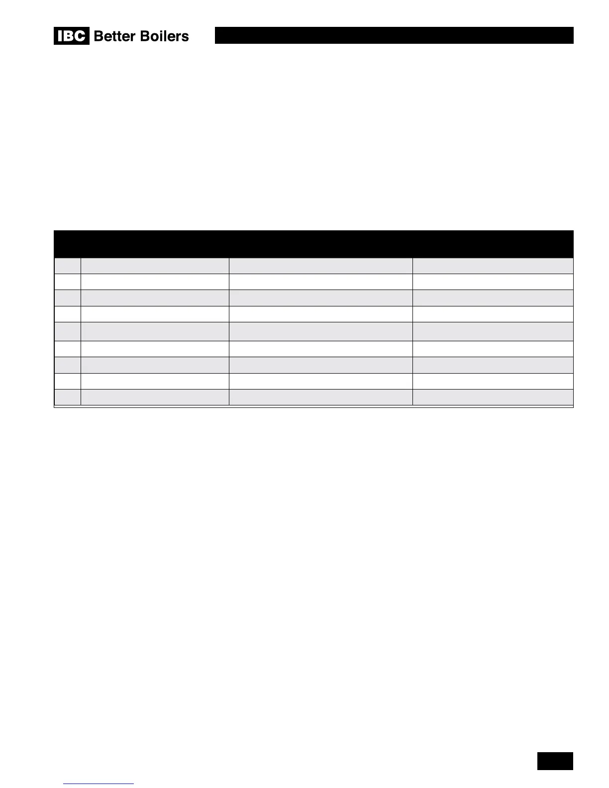
The following table displays the required connection specications for each model.
Figures 1A and 1B show outer case dimensions, piping and electrical holes. Refer to
these gures to help with nding a suitable location for the boiler. See also Section 1.3
Location.
DESCRIPTION SL 26-260 G3 SL 40-399 G3
A Flue Outlet 3” Schedule 40 4" Schedule 40
B Combustion Air Inlet 3” Schedule 40 4" Schedule 40
C Safety Relief Valve and Air Vent 3/4" NPT - F 3/4" NPT - F
D Touchscreen display 2-1/4” x 4” 2-1/4" x 4"
E Water Outlet 1-1/2” NPT-M 1-1/2" NPT - M
F Water Inlet 1-1/2” NPT-M 1-1/2" NPT - M
G Knock-outs (8) 1/2” 1/2"
H Gas Inlet 3/4” NPT-F 3/4" NPT - F
I Condensate Outlet 3/4” Hose 3/4" Hose
Table 1: Connections

 Loading...


