INSTALLATION AND OPERATION INSTRUCTIONS
1-22
SL 80-399 MODULATING GAS BOILER
SL 26-260 G3, SL 40-399 G3 MODULATING GAS BOILERS
Fluid ll is most often accomplished by using a boiler regulator & ll valve set at 12 psig
or more, with the appropriate backow prevention device as required by local code. This
is acceptable in areas where municipal water or well water has been treated and ltered
to remove excessive minerals and sediment, and water chemistry is known to be suitable
for closed loop hydronic systems. In areas where water quality is in question, or when
chemical treatment or glycol is required, other options should be considered. Follow the
applicable codes and good piping practice.
There are a number of boiler feed and pressurization devices on the market today that
may be a better choice than a raw water ll from the mains. When regular maintenance
requires relief valve blow-off, the discharge may be directed back into the pressurization
unit for recycling of boiler uid and chemicals back into the system. In buildings that may
be unoccupied for long periods of time, pressurization units are useful to prevent ood
damage should leakage occur from any component in the system. An additional benet is
that backow prevention devices are not required when using these devices.
Do not place any water connections above the boiler; leaks can damage the fan and
controls. If needed, create a shield over the top of the cover, but allow clearance for airow
and service access.
For best results, use a Primary/Secondary piping system, with a pumped boiler loop using
2" piping. Refer to Tables 5A and 5B for boiler head loss information.
For example, the minimum ow rate required through the heat exchanger is 20 gpm and
a maximum of 45 gpm is allowed. Primary/Secondary piping ensures adequate ow and
de-couples Δ°T issues (boiler vs. distribution). Aim for a 20° to 30° F Δ°T across the heat
exchanger at high re (there is a boiler protection throttle fence limiting the Δ°T to 40°F).
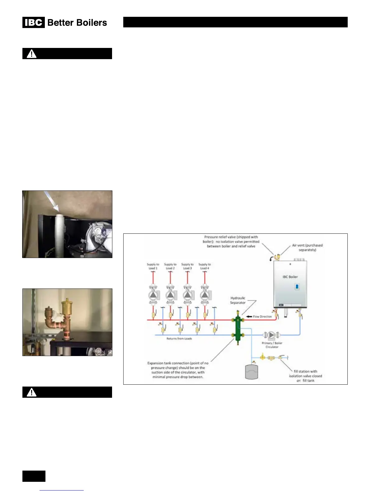
Figure 27: Primary/Secondary piping concept with hydraulic separator
The boilers can supply multiple heating loads with compatible supply temperature
requirements. Always ensure that loads sensitive to high temperatures are protected using
means such as mixing valves.
Supply stack upper tapping - 3/4”
FIP to accept relief valve and air
vent assembly
Relief valve and air vent assembly
(recommended conguration)
WARNING
Close ll valve after any addition
of water to the system, to reduce
risk of water escapement.
NOTE
Full sized application drawings
can be downloaded from our web
site.
www.ibcboiler.com

 Loading...


