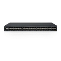
Forty-eight 10/100/1000BASET ports are located on the front panel. These ports
accept supported optical or copper SFP or SFP+ transceivers, or direct attach
cables (DACs). Transceivers must be purchased separately.
For the available transceivers and direct attach cables (DACs) for the switch, see
https://www-01.ibm.com/products/hardware/configurator/americas/bhui/launchNI.wss.
SFP+ ports
Four 10 GbE Small Form-factor Pluggable Plus (SFP+) ports are located on the
front panel. These ports accept approved optical or copper SFP or SFP+
transceivers. Transceivers are not included with the G8052 switch unit.
Console port
The RS-232 (mini-USB) serial console port is located on the front panel. The
following table describes the pinouts for the mini-USB port.
Table 1. Console port pin assignments
Pin number Function
Pin 1 No connect
Pin 2 RS232-SIN
Pin 3 RS232_SOUT
Pin 4 No connect
Pin 5 Ground
The console cable provides an RJ-45 connector (see Table 2 for RJ-45 pin
assignments). A retention clip is available to secure the console connection.
The following table describes the pin assignments for the RJ-45 connector on the
console cable.
Table 2. RJ-45 connector pin assignments
Pin number Function
1 RTS (Request To Send)
2 DTR (Data Terminal Ready)
3 TxD (Transmit Data)
4 GND (Ground)
5 GND (Ground)
6 RxD (Receive Data)
7 DSR (Data Set Ready)
8 CTS (Clear To Send)
The following items are also included with the console cable.
v Category 5 patch cable
v RJ-45 to female DB9 adapter
To connect a computer or terminal to the switch, first connect the console cable to
the mini-USB port on the front panel. Connect one end of the patch cable to the
RJ-45 port on the console cable, and the other end of the patch cable to the
RJ-45-to-DB9 adapter (see the following illustration).
Chapter 1. Introduction 7
 Loading...