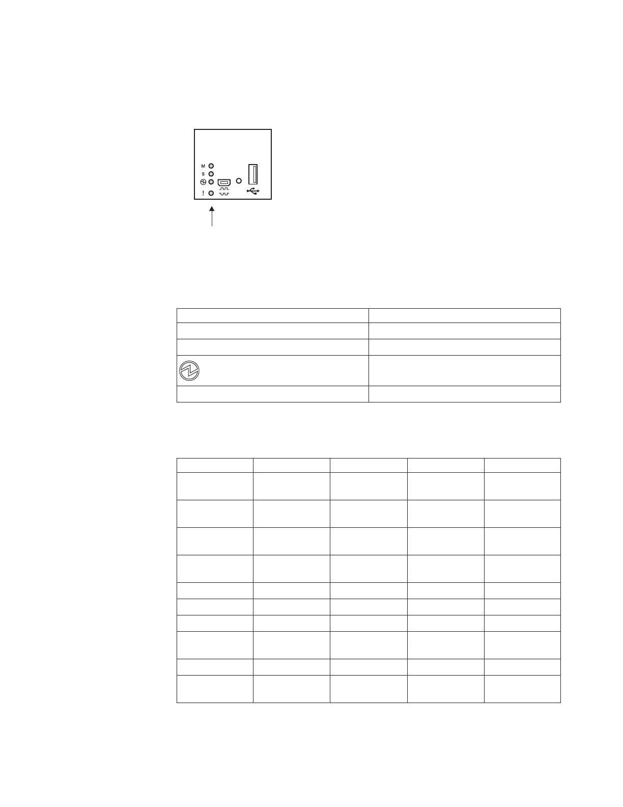
Switch LEDs
Two LED stacks provide system status and port link status. The following illustration
shows the system LEDs.
The system LEDs are described in the following table.
Table 3. System LEDs
Symbol Description
M Stacking master indicator
S Stacking member indicator
Power supplies and power input status
! Service indicator
The following table describes the system LEDs.
Table 4. System LED descriptions
Function Master Member Power supply Service
Total Power
Failure
Off Off Off Off
Service Required Flash green Flash green
(Note 1)
Flash green
(Note 2)
Flash blue (Note
3)
Power Supplies
OK
Not applicable Not applicable Steady green Not applicable
Power Supply
Failure
Not applicable Not applicable Flash green Not applicable
Fans OK Not applicable Not applicable Not applicable Not applicable
Fan Failure Not applicable Not applicable Not applicable Not applicable
Stack Master On Off Not applicable Off
Stack
Backup/Member
Off On Not applicable On
Stack Error On On Not applicable On
Non-Stack
Member
Off Off Not applicable Off
RackSwitch G8052
System status LEDs
Figure 5. System status LEDs
Chapter 1. Introduction 9