Chapter 3. System overview
IBM COS Medium and Large Disk Enclosure, and front, top, and rear panels are described.
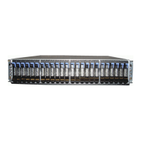
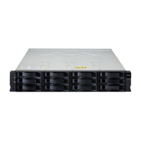
Enclosure chassis
An overview of the Disk Enclosure.
The Disk Enclosure consists of a sheet metal enclosure with integrated boards and a module runner
system. The enclosure contains a drive channel and a controller channel, and features removable top
cover lids. Enclosure top and rear panels provide access to plug-in modules known as customer-
replaceable units (CRUs). Each enclosure is made of sheet steel that is bonded together using rivets,
welding, and other forced contact methods. The metal surfaces are free from non-conductive coatings
and paint.
• The chassis has a 1.2 m rack mounting that enables it to be installed onto standard 1.2 m racks, and
uses four EIA units of rack space (7 inches) for a 4U enclosure. Optional lift handles on the chassis side
walls facilitate hoisting and installation. See Figure 23 on page 29.
• The Cable Management Arm (CMA) routes cables from the controller channel and external connections,
and secures them for in-rack servicing of the installed enclosure. The rails slide outward from the
installed position.
• An internal high-speed harness ensures routing of cables controlled to specication; protects the
interfaces between cables and connectors; and provides a connector system designed for positive
(latched) mating.
• The drive channel bus-bar distributes power from the power mid-plane to 24 hard disk drive base-
planes.
• Four 24 hard disk drive base-plane boards support 96 disk drive connections in the drive channel.
• A ten hard disk drive base-plane board supports 10 disk drive connections in the controller channel.
• The enclosure top panel provides access to LFF (with adapter) disks, held vertically. Each drive slot
holds a plug-in drive carrier module. The top panel also provides access to the HS expander and
controller fan CRUs.
Note: Top panel enclosure lids A and B slide out, and can be temporarily removed for a servicing event.
See Figure 9 on page 11.
• Four removable HS expanders connect to 24 hard disk drive base-planes via expander link cards,
providing high availability.
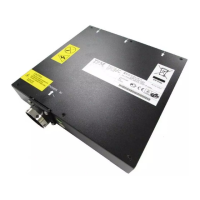
• Within the controller channel compartment, channel fans provide additional cooling the IOM.
• Within the rear panel, the chassis assembly is populated with two PSUs, four system fans, are an IOM,
and the flattened cable coils held by the bracket assembly on the CMA shelf (atop system fan sheet
metal).
Enclosure conguration
Medium and Large Disk Enclosure are described.
The IBM COS Medium and Large Disk Enclosures support a 4U (rack space) chassis – see the two gures
below. The large Disk Enclosures holds up to 106 low prole (1-inch high) 3.5 inch form factor disk drive
modules in a vertical orientation and the medium Disk Enclosure holds 53 disks in the same orientation.
Alternatively, disk slots can hold a low prole (5/8-inch high) 2.5 inch form factor disk with an adapter
within the large form factor carrier.
Each individual disk drive is hot pluggable and replaceable on site. Drive modules must be installed during
system setup.
©
Copyright IBM Corp. 2020, 5