Parts/Test Point Locations 111
Power Supply Connectors and
Voltages
Refer to the following figures when checking for
voltages on power supply cable connectors.
When checking voltages, the power supply fan must
be running. To power-on the power supply without
using the on/off switch, use a screwdriver or other tool
to short the connector JP3 (with the switch cable
disconnected from the connector on the syste
board), or use a connection (jumper) to short the
black and green wires of the 20-pin connector on
power supply.
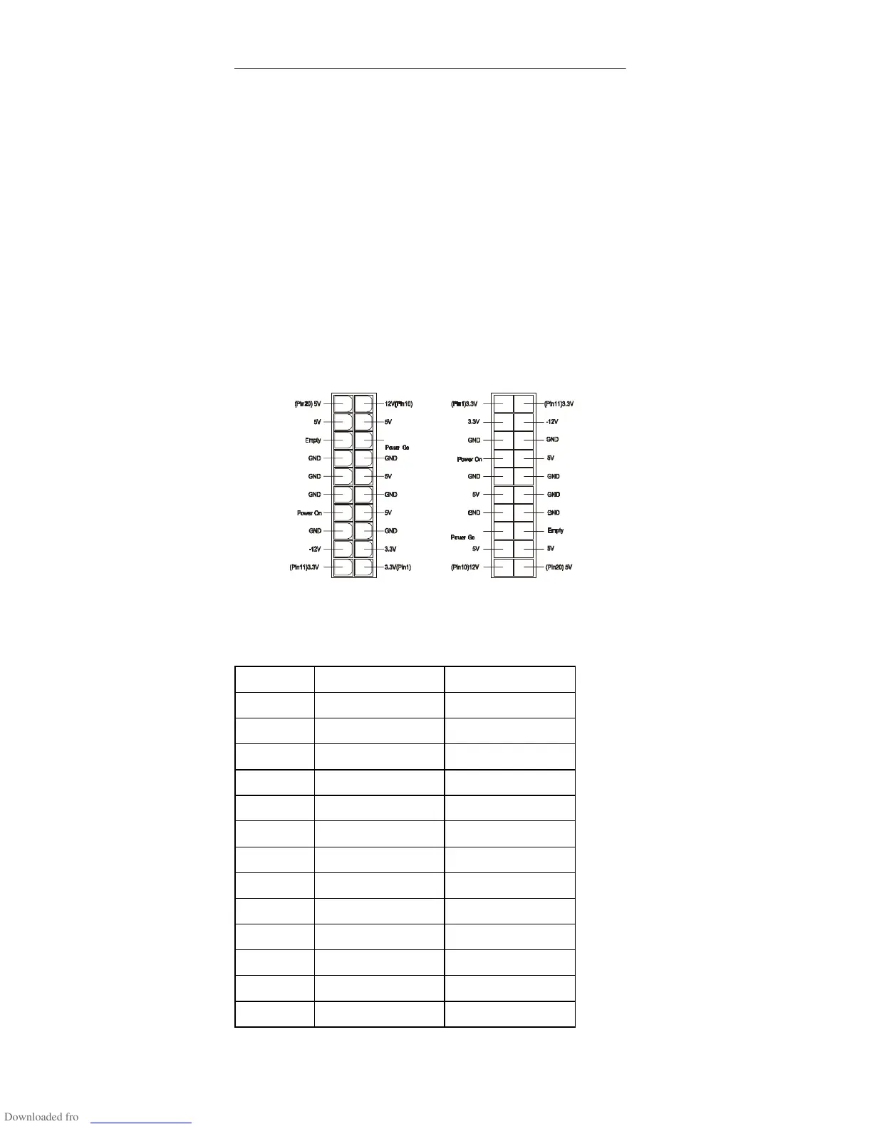
20-pin Power Connector
Pin-hole side view Cable side view
Power Supply Output Pin Assignment
Pin Voltage Cable Color
1 +3.3Vdc Orange
2 +3.3Vdc Orange
3Ground Black
4 Power-on Red
5Ground Black
6+5Vdc Red
7Ground Black
8 Power Good Gray
9+5Vdc Purple
10 +12Vdc Yellow
11 +3.3Vdc Orange
12 -12Vdc Blue
13 Ground Black
 Loading...


