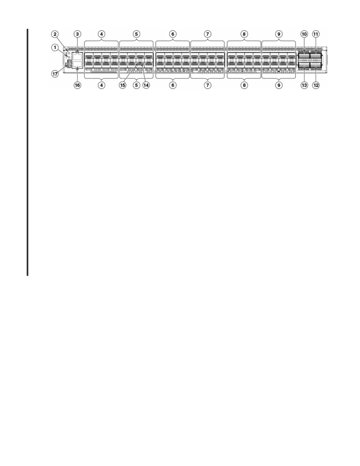
Figure 1. Port-Side View of SAN64B-6 Version 1
1. System Status LED
2. System Status LED
3. UART RJ-45 Serial Console Port
4. SFP+ FC (four upper and four lower) Ports 0–7
5. SFP+ FC (four upper and four lower) Ports 8–15
6. SFP+ FC (four upper and four lower) Ports 16–23
7. SFP+ FC (four upper and four lower) Ports 24–31
8. SFP+ FC (four upper and four lower) Ports 32–39
9. SFP+ FC (four upper and four lower) Ports 40–47
10. QSFP Port 0 (FC Ports 48–51)
11. QSFP Port 2 (FC Ports 56–59)
12. QSFP Port 3 (FC Ports 60–63)
13. QSFP Port 1 (FC Ports 52–55)
14. SFP+ (lower) Port 14 Status LED
15. SFP+ (upper) Port 10 Status LED
16. 1000/100/10Bb/s RJ-45 Ethernet Management Port
17. USB Port
The following illustration shows the port-side view of the SAN64B-6 Version 2 Fibre Channel switch.
Chapter 1. Introducing the SAN64B-6
3

 Loading...