Identifying the airflow direction
The power supply and fan assemblies are identied by the following airflow directions:
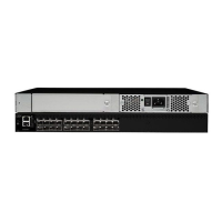
• Intake power supply and fan assembly with an orange "I" label or without any label: Pulls air from
the nonport-side of the switch and exhausts it out the port side.
– Nonport-side air intake
– Port-side air exhaust
– Back-to-front (nonport-side to port-side)
airflow
– Part numbers ending with -R
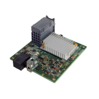
• Exhaust power supply and fan assembly with a green "E" label: Pulls air from the port side of the
switch and exhausts it out the nonport-side.
– Nonport-side air exhaust
– Port-side air intake
– Front-to-back (port-side to nonport-side)
airflow
– Part numbers ending with -F
AIR_FLOW and ENCR Error Monitoring
Starting with FOS 9.0.0, MAPS added support for the following monitoring systems:
• FAN_AIRFLOW_MISMATCH
• ENCR_BLK
• ENCR_DISC
• ENCR_SHRT_FRM
Power supply and fan assembly unit fault indicators
Use one of the following methods to determine the status of the power supply and fan assemblies:
• Check the power supply and fan assembly status LED. See “Interpreting nonport-side LEDs” on page
57.
• In Web Tools, click the Power Status icon.
• Enter the psShow command at the prompt to display power supply and fan assembly status, as shown
in the following example:
Device:admin> psshow
Power Supply #1 is OK
Power Supply #2 is OK
Power supply and fan assembly task guide
You can perform an easy set of steps to install or replace a power supply and fan assembly or to replace
both power supply and fan assemblies. By default, both of the power supply and fan assemblies are
installed in the device.
Installing an additional power supply and fan assembly (hot-install)
If your device is up and running with a single power supply and fan assembly and you want to install an
additional power supply, complete the following steps.
Chapter 7. Power supply and fan assembly
63