Note: When the expansion enclosure is shipped, the 4U and 1U fascia are not
installed. You must install them as part of the initial installation process.
Procedure
1. Use the slide rails to pull the enclosure out of the rack, as described in
“Removing an expansion enclosure from a rack: 2077-92F” on page 95.
Attach the front (4U) fascia
2. Align the front 4U fascia with the enclosure so that the thumbscrews go
through the holes on each side. As Figure 69 on page 82 shows, this action
aligns the screw holes on the back of the fascia with the screw holes on the
front flange of the enclosure.
3. Replace the four screws to reattach the 4U fascia. Secure the screws from the
back of the flange and into the rear of the fascia. Each side of the 4U fascia
contains two screws.
Attach the bottom (1U) fascia
4. Reattach the bottom 1U fascia that covers the power supply units (PSUs). Align
the fascia with the enclosure and gently push it until it clicks into place on the
chassis, as shown in Figure 69 on page 82.
Align the tab on each side of the 1U fascia with the corresponding slots on the
enclosure flange. Pins on each flange must also align with a hole in each side of
the 1U fascia.
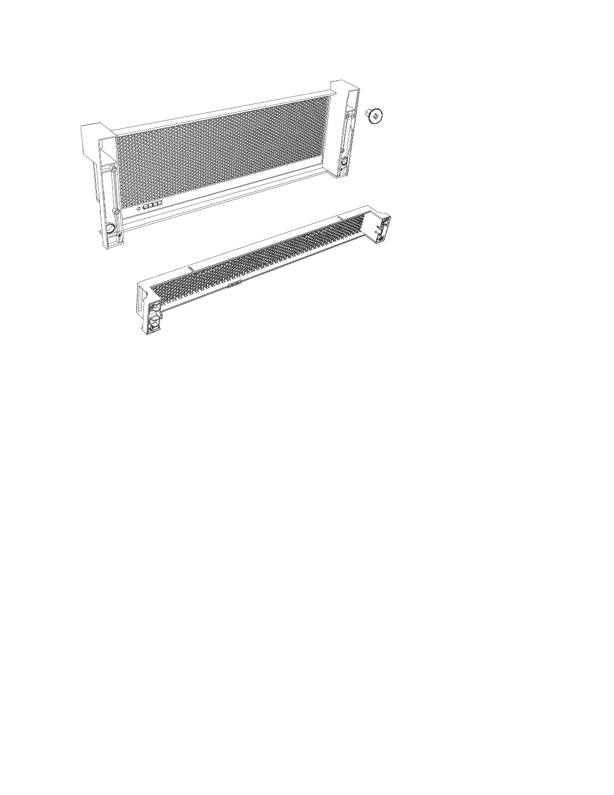
Figure 68. Fascia components on the expansion enclosure
Chapter 2. Installing the system hardware 81

 Loading...


