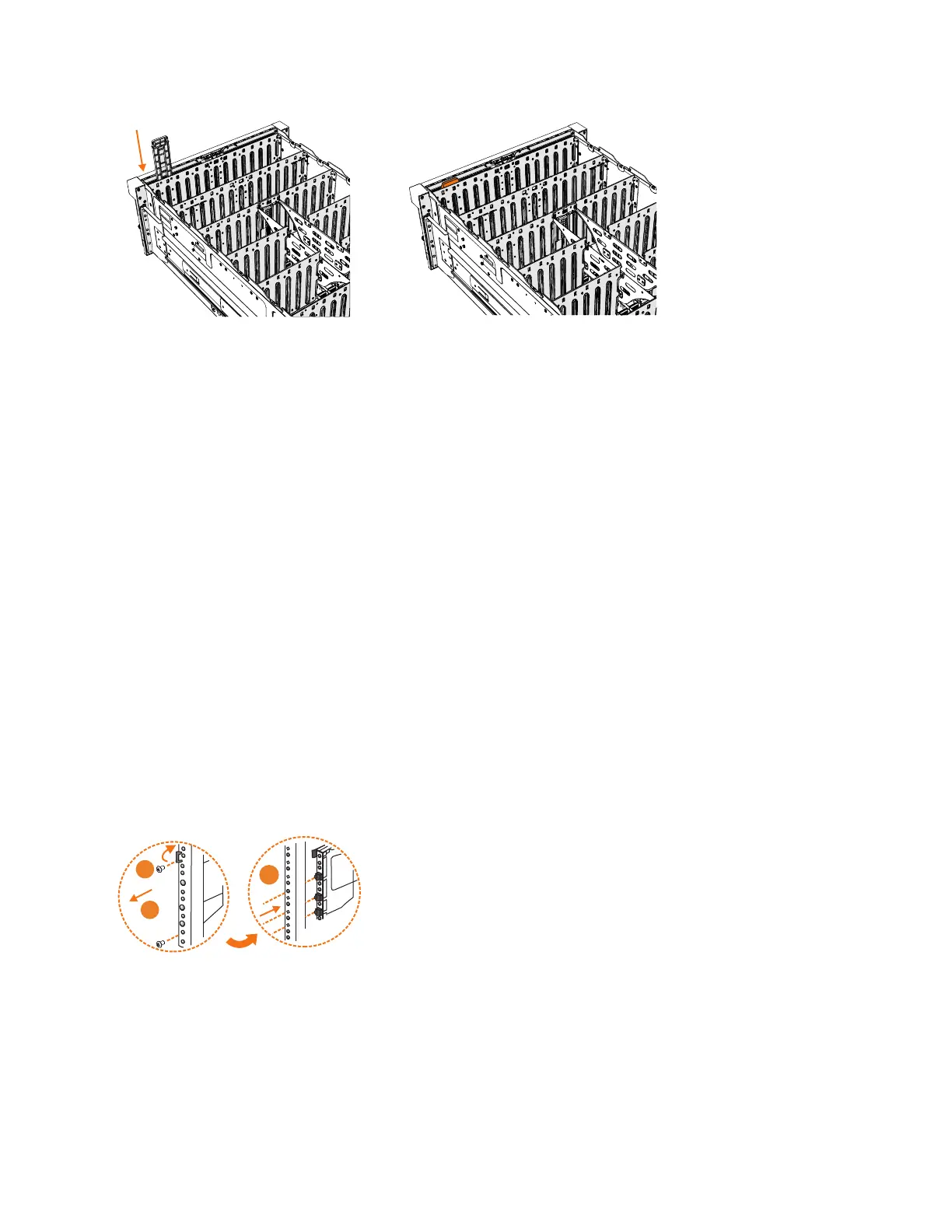
3. Insert the display panel assembly until it clicks into position.
4. Replace the top cover, as described in “Installing or replacing the top cover:
2077-92F” on page 71.
5. Ensure the LEDs on the display panel are lit correctly. See “Storwize V5000
Gen2 2077-92F expansion enclosure LEDs and indicators” on page 135 for
details.
Removing the support rails: 2077-92F
You can remove the support rails for the 2077-92F expansion enclosure.
About this task
This task assumes the following conditions:
v The cable management arm is removed, as described in “Removing or moving
the cable-management arm: 2077-92F” on page 61.
v The expansion enclosure is removed from the rack, as described in “Removing
an expansion enclosure from a rack: 2077-92F” on page 95.
Procedure
1. Remove the two screws that attach the outer rail section to the front bracket
assembly, as shown in Figure 110.
2. Remove the rail section by pulling it away from the front bracket, as shown in
Figure 110.
3. Remove the two screws that attach the inner rail section to the rear bracket, as
shown in Figure 111 on page 128.
Figure 109. Installing the display panel assembly
Figure 110. Remove the rail assembly from the front frame bracket
Chapter 2. Installing the system hardware 127
 Loading...


