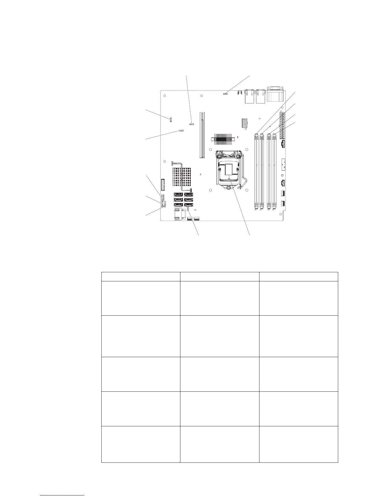
System-board jumpers
The following illustration shows the jumpers on the system board.
DIMM 1
DIMM 2
DIMM 3
DIMM 4
Microprocessor
Clear CMOS
jumper (JP 1)
BIOS boot backup
jumper (J 2)P
TPM physical
presence
jumper (JP 10)
ME recovery
jumper (JP 8)
ME flash override
jumper (JP 9)
TPM initialization
jumper (JP 11)
Low security
jumper (J 19)P
IMM SPI HALF ROM
enable jumper (J 12)P
The following table describes the jumpers on the system board.
Table 2. System board jumpers
Jumper number Jumper name Jumper setting
JP1 Clear CMOS jumper
v Pins 1 and 2: Keep CMOS
data (default)
v Pins 2 and 3: Clear CMOS
data
JP2 BIOS block backup jumper
v Pins 1 and 2: Boot from
primary BIOS page
(default)
v Pins 2 and 3: Boot from
backup BIOS page
JP8 ME recovery jumper
v Pins 1 and 2: Normal
(default).
v Pins 2 and 3: Activate ME
recovery.
JP9 ME flash override jumper
v Pins 1 and 2: Normal
(default).
v Pins 2 and 3: Override ME
flash.
JP10 Trusted Platform Module
(TPM) physical presence
jumper
Pins 1 and 2: Enable TPM
physical presence (default)
Pins 2 and 3: Disable TPM
physical presence
22 IBM System x3250 M4 Type 2583: Installation and User’s Guide

 Loading...


