3. Slide the top cover toward the front of the server.
4. Make sure that the top cover correctly engages all the inset tabs on the server.
5. Install the server into the rack enclosure and tighten the two front thumbscrews
to secure the server in the rack.
6. Reconnect the external cables and power cords.
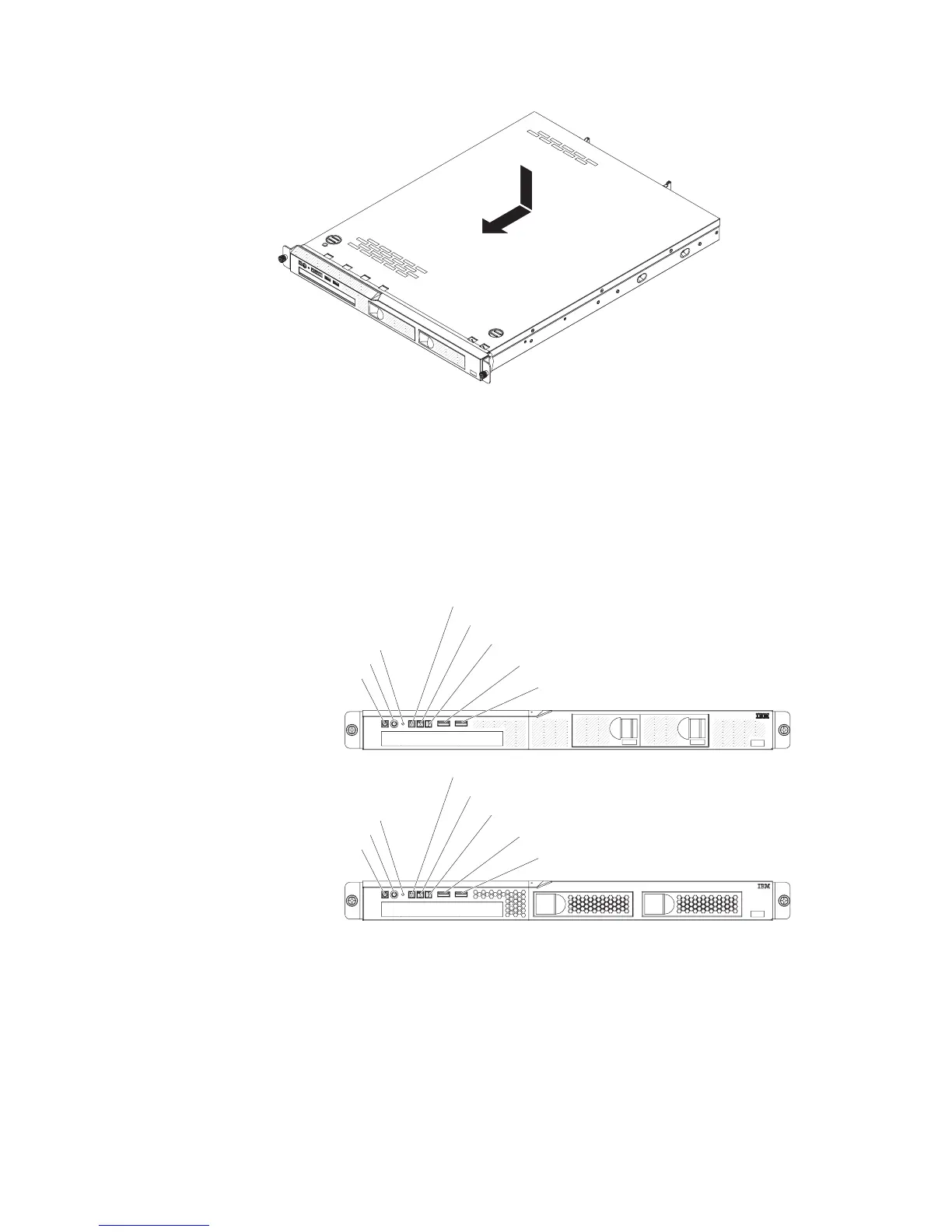
Connecting the cables
The following illustration shows the locations of the input and output connectors on
the front of the server.
Power-on LED
Power-control button
Reset button
Hard disk drive activity LED
Locator LED
System-error LED
USB 1 connector
USB 2 connector
Power-on LED
Power-control button
Reset button
Hard disk drive activity LED
Locator LED
System-error LED
USB 1 connector
USB 2 connector
The following illustration shows the locations of the input and output connectors on
the rear of the server.
48 IBM System x3250 M4 Type 2583: Installation and User’s Guide

 Loading...


