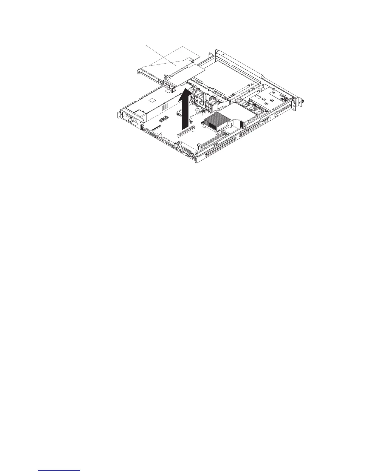
Riser-card
assembly
4. Grasp the riser-card assembly at the rear edge and lift to remove it from the
server. Place the riser-card assembly on a flat, static-protective surface.
5. Remove the expansion-slot cover from the slot that you intend to use.
Attention: PCI expansion-slot covers must be installed on all vacant slots.
This maintains the electronic emissions characteristics of the server and
ensures proper cooling of server components.
6. Touch the static-protective package that contains the adapter to any unpainted
metal surface on the server. Then, remove the adapter from the
static-protective package. Avoid touching the components and gold-edge
connectors on the adapter.
7. Place the adapter, component side up, on a flat, static-protective surface and
set any jumpers or switches as described by the adapter manufacturer, if
necessary.
8. To install the adapter in the riser-card assembly, carefully grasp the adapter by
its top edge or upper corners, and align it with the expansion slot; then, press
the adapter firmly into the expansion slot.
9. Follow the cabling instructions, if any, that come with the adapter.
10. Carefully align the riser-card assembly with the guides on the rear of the
server and with the riser-card connectors on the system board; then, press
down on the assembly. Make sure that the riser-card assembly is fully seated
in the riser-card connector on the system board.
11. If you are installing a ServeRAID 8s controller, complete the following steps:
a. Disconnect the existing SAS/SATA controller signal cable from the hard
disk drive backplane and from the controller; then, remove the cable from
the server.
b. In a server with 2.5-inch drives, route the ServeRAID 8s signal cable as
shown in the following illustration and connect it to the hard disk drive
backplane.
Chapter 2. Installing optional devices 21