4 - 6
TRANSMITTER ADJUSTMENTS (continued)
FM
DEVIATION
AM
MODULATION
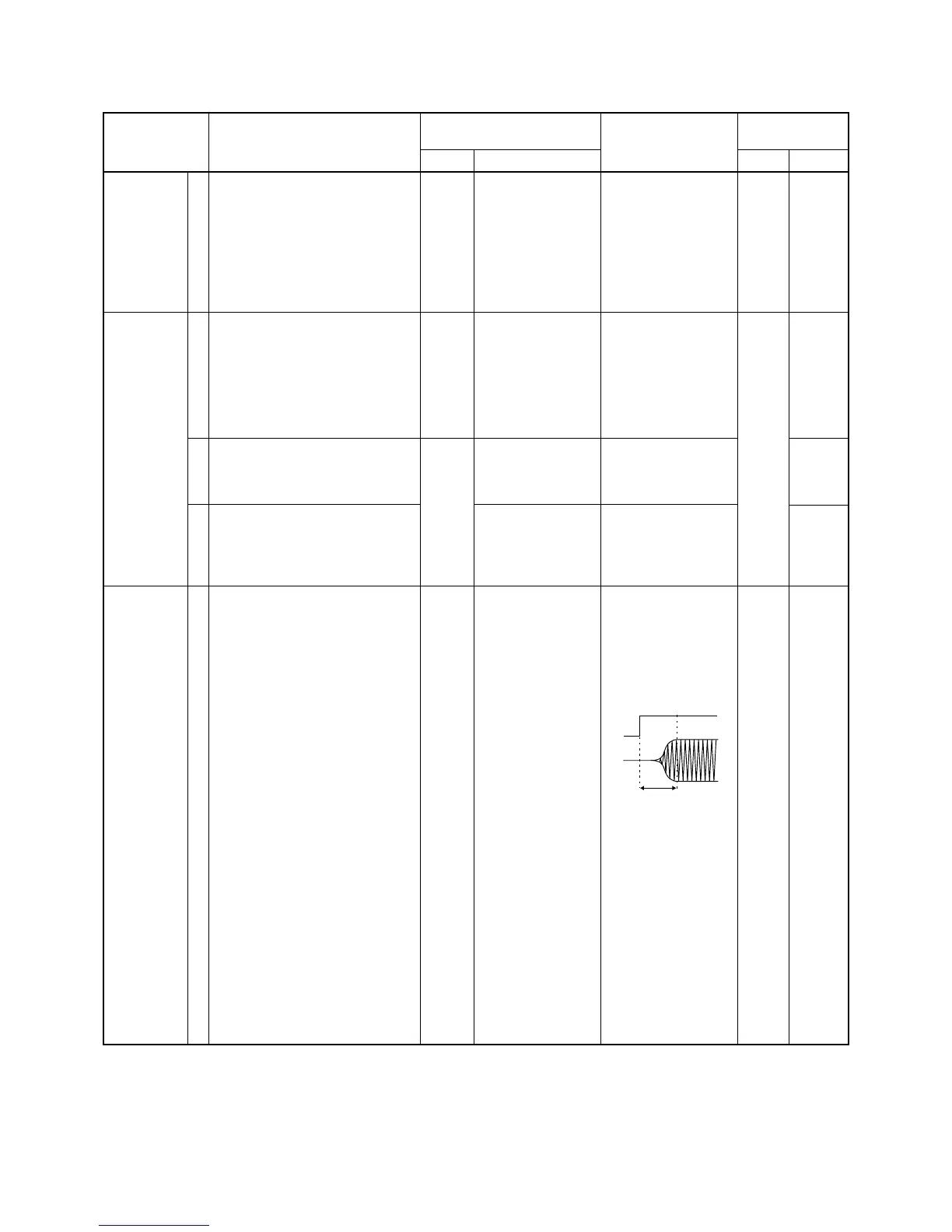
CW
CARRIER
LEVEL
ADJUSTMENT
ADJUSTMENT ADJUSTMENT CONDITION
MEASUREMENT
VALUE
POINT
UNIT LOCATION UNIT ADJUST
1
1
2
3
1
• Display frequency: 29.10000 MHz
• Mode : FM
• [RF POWER] : H
• [TON] : OFF
• [MIC GAIN] : 5
• Connect an audio generator to
[MIC] connector and set as:
1 kHz/30 mV
• Transmitting
• Display frequency
: 14.10000 MHz
• Mode : AM
• [RF POWER] : H
• [MIC GAIN] : 5
• Disconnect the plug from J2 on the
MAIN unit.
• Apply no signal to [MIC] connector.
• Transmitting
• Connect the plug to J2 on the MAIN
unit.
• Apply no signal to [MIC] connector.
• Transmitting
• Pre-set R2618 to 9 o’clock position.
• Connect an audio generator to
[MIC] connector and set as:
1 kHz/30 mV
• Transmitting
• Display frequency: 14.10000 MHz
• Mode : CW
• [RF POWER] : H
• [KEY SPEED] : 60
• [BRK] : BK
(semi break-in)
• CW paddle : n
• Connect an RF power meter to
[ANT] connector.
• Transmit dots for a while using a
paddle.
Rear
Panel
MAIN
Rear
Panel
Connect an FM devi-
ation meter to [ANT]
connector via an
attenuator.
Connect an osillo-
scope to check point
CP1302.
Connect an RF
power meter to [ANT]
connector.
Connect a modula-
tion analyzer to [ANT]
connector via an
attenuator.
Connect an osillo-
scope to check point
CP1851 and [ANT]
connector.
±4.5 kHz
400 mVp-p
3.5 W
90 % (–peak) modula-
tion
At the point where the
CW carrier completely
comes up in a 10
msec. delay after
CP1851 voltage comes
up.
MAIN
MAIN
MAIN
R2621
R1811
R2707
R2618
R1853