3 - 10
3-6-3 MAIN UNIT
3-6-4 CTRL AND PLL UNITS
3-7 LOGIC CIRCUITS
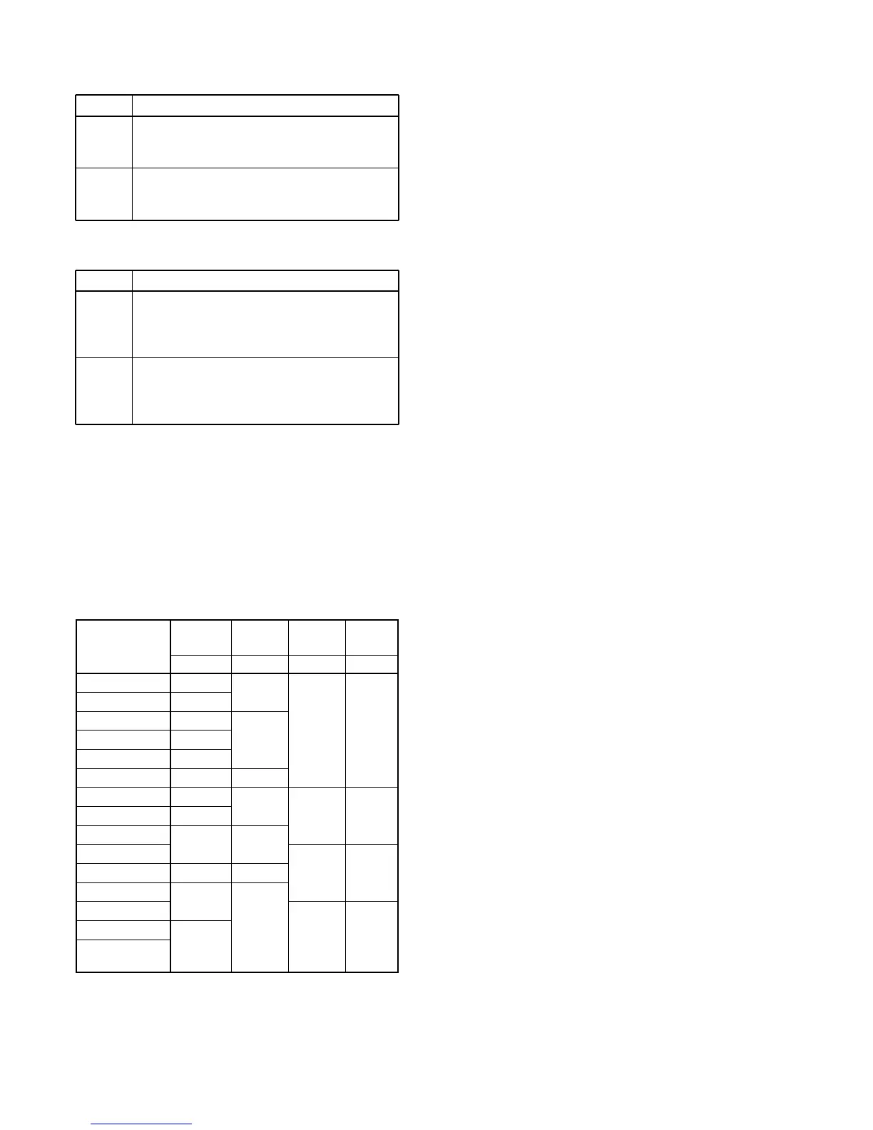
3-7-1 BAND SELECTION DATA
(RF, CTRL AND PLL UNITS)
To select the correct bandpass, low-pass filters and VCOs
on the RF, FILTER and PLL units, the main CPU (MAIN unit,
IC3501) outputs the following band selection data via the I/O
expander (RF unit, IC901, IC902, CTRL unit, IC11) or DDS
IC (PLL unit, IC101, IC401) depending on the displayed fre-
quency.
The D/A convertor (MAIN unit, IC3751) output signal from
pin 7 is amplified at IC101b (pins 5–7) to obtain the band
voltage for external equipment via the [ACC 2] connector pin
4.
0.003–1.599999
1.6–1.999999
2.0–2.999999
3.0–3.999999
4.0–5.999999
6.0–7.999999
8.0–10.999999
11.0–14.999999
15.0–19.999999
20.0–21.999999
22.0–29.999999
30.0–44.999999
45.0–49.999999
50.0–54.000000
54.000001–
60.000000
Frequency
IC901, IC902
IC11 IC101 IC401
[MHz]
(RF unit) (CTRL) (PLL) (PLL)
BPF LPF VCO-A VCO-B
B0
B1
B2
B3
B4
B5
B6
B7
B8
B9
B10W
B10
B10W
L1S
L2S
L3S
L4S
L5S
L6S
L7
VA1S
VA2S
VA3S
VA4S
VB1S
VB2S
VB3S
VB4S
LINE
R8V
T8V
DESCRIPTION
Receive 8 V converted from the 14 V line and
regulated by the R8V regulator circuit (Q601,
Q602, D601).
Transmit 8 V converted from the 14 V line and
regulated by the T8V regulator circuit (Q611,
Q612, D611).
LINE
5V
5V
DESCRIPTION
Common 5 V for the antenna tuner CPU (CTRL
unit; IC5) and the EEPROM (CTRL unit; IC6),
converted from the 14 V line and regulated by
the +5 regulator circuit (CTRL unit; IC13).
Common 5 V for each of the PLL-A and PLL-B
circuits regulated from the 8 V line and regulated
by the +5 regulator circuit (PLL unit; IC382: PLL-
A, IC682: PLL-B).