SECTION 3 DISASSEMBLY INSTRUCTIONS
3 - 1
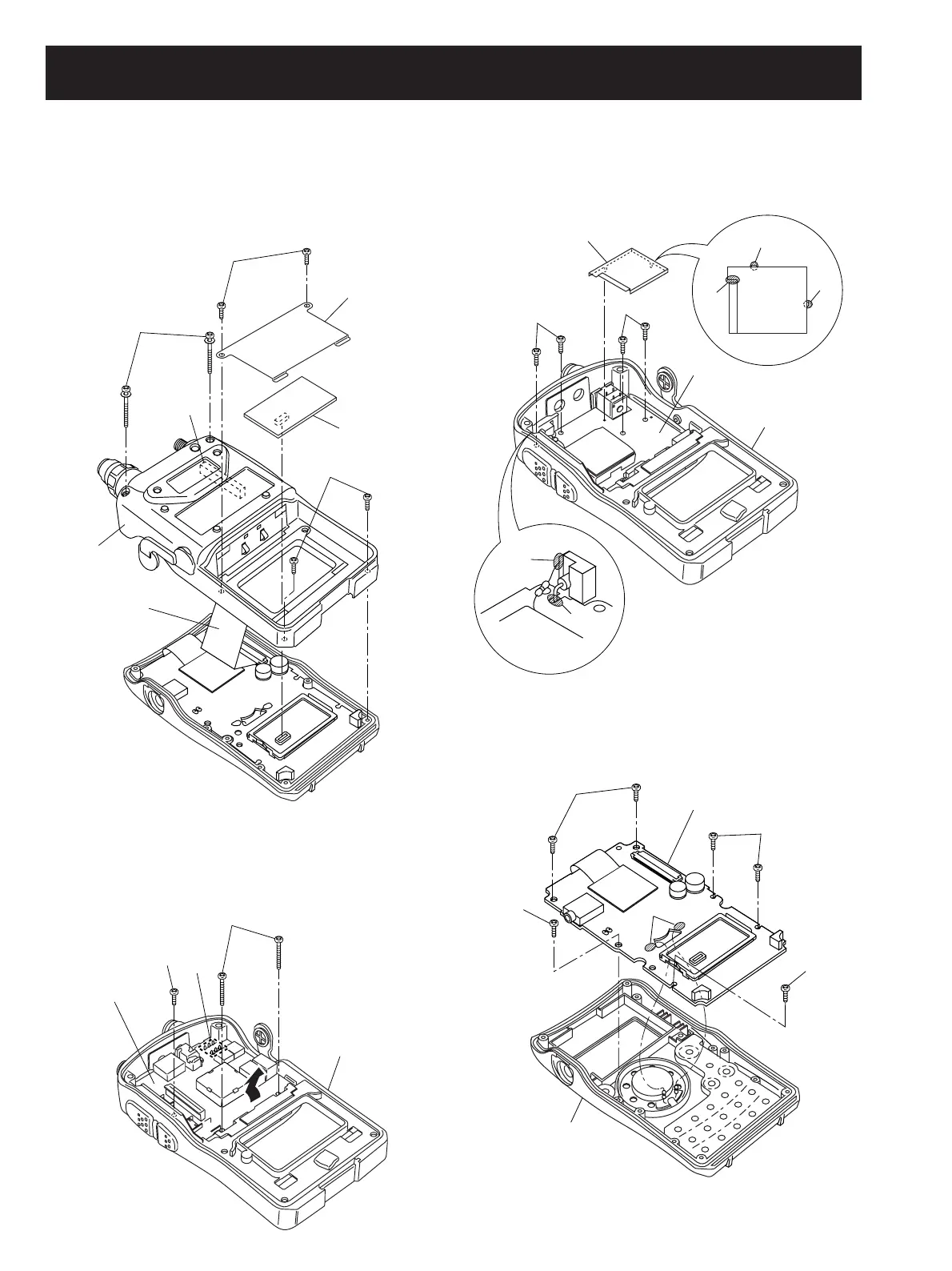
• Removing the rear panel
1 Unscrew 2 screws A and remove the plate B.
2 Remove the CODEC unit (UT-121) if installed. (See the
page 4-1 “2” for uninstallation)
3 Unscrew 2 screws C and 2 screws D.
4 Disconnect the flat cable E from MAIN unit J702.
5 Remove the rear panel.
• Removing the MAIN unit
1 Unscrew the screw A and 2 screws B.
2 Unsolder 6 points C.
3 Remove the MAIN unit from the rear panel in the direction
of the arrow.
D
E
B
A
C
Rear panel
CODEC unit
(UT-121)
J702
LOGIC unit
A
B
B
B
B
Front panel
B
A
MAIN unit
Rear panel
C
A
A
D
D
B
B
B
RF unit
Rear panel
C
• Removing the LOGIC unit
1 Unsolder 2 points A.
2 Unscrew 6 screws B and remove the LOGIC unit from the
front panel.
• Removing the RF unit
1 Unsolder 2 points A.
2 Unsolder 3 points B and remove the shield plate C.
3 Unscrew 4 screws D and remove the RF unit from the
rear panel