5-1 RECEIVER CIRCUITS
This transceiver has two receiving lines called A_BAND and B_
BAND for dualwatch capability. A_BAND corresponds to FM/WFM/
AM mode receiving within 0.495–999 MHz range, and B_BAND
corresponds to FM/FM-N/AM/DV mode receiving within 118–174
MHz and 350–470 MHz ranges.
5-1-1 RF CIRCUITS (RF UNIT)
This transceiver has six RF circuits to provide wide receiving range.
The received signals from the antenna connector (CHASSIS; J1)
are applied to each RF circuit for the frequency coverage, and
amplified within the frequency coverage.
• While receiving 0.495–76 MHz
The received signals of 76 MHz and below are passed through the
low-pass filter (LPF; L200, L201, C201–C204) via the two LPFs
(L1–L3, C1–C6; L5–L7, C10–C14), attenuator (D10) and band
switch (D200).
The 0.495–30 MHz band signals are passed through the band
switch (D201), then applied to the RF amplifier (Q200) via the
low-pass filter (L202, L203, C205–C209). The 30–76 MHz band
signals are applied to the tuned RF amplifier (Q250, D252, D255)
via the band switch (D250).
The amplified signals are applied to the A_BAND 1st mixer (IC900,
pin 1) via the band switches (D203 or D256, D707).
- 0.495–76 MHz -
• While receiving 76–118 MHz or 174–260 MHz
The 76–118 MHz band signals are passed through the two LPFs
(L1–L3, C1–C6; L5–L7, C10–C14), attenuator (D10) and low-pass
filter (L300, L301, C301–C305) via the band switch (D300).
The 174–260 MHz band signals are passed through the LPF (L1–
L3, C1–C6), HPF (L4, C7–C9), attenuator (D7) and high-pass filter
(HPF; L302, L303, C306–C310) via the band switch (D302).
The filtered signals are applied to the tuned RF amplifier (Q300,
Q301, D305, D307, D308) via the band switch (D301/D303).
The amplified signals are applied to the A_BAND 1st mixer (IC900,
pin 1) via the band switches (D311, D707).
SECTION 5 CIRCUIT DESCRIPTION
5 - 1
LPF
LPF
D255
Tuned RF amplifier
D707
D256
D203
Q250
Q200
to the A_BAND
1st mixer
(IC900, pin 1)
0.495
-
30 MHz
D252
RF
amp.
ATT
D201
0.495
-
76 MHz
D250
D200
D10
2 LPFs
from the
antenna
30
-
76 MHz
LPF
LPF
Tuned RF amplifier
D307, D308 Q300 D305Q301
D707
to the A_BAND
1st mixer
(IC900, pin 1)
D311
76
-
118 MHz
LPF
D301
D10
D300
LPFHPF
174
-
260 MHz
HPF
AT T
AT T
D303
D7
D302
from the
antenna
- 76–118 MHz or 174–260 MHz -
Tuned RF amplifier 2 LPFs
D402, D403 Q401 D401
D509
to the A_BAND
1st mixer
(IC900, pin 1)
D405
Tuned RF amplifier
D451, D452 Q450 D450
D400
to the B_BAND
1st mixer
(MAIN UNIT; IC50, pin 1)
D454
ATT
D10
from the
antenna
BPF
Q400 118
-
174 MHz
RF
amp.
LPF
from the
antenna
Tuned RF amplifier
260
-
350 MHz, 470
-
600 MHz
D505, D506
D7
HPF LPF ATT
Q500 D502 Q501
D509
to the A_BAND
1st mixer
(IC900, pin 1)
D508
D500
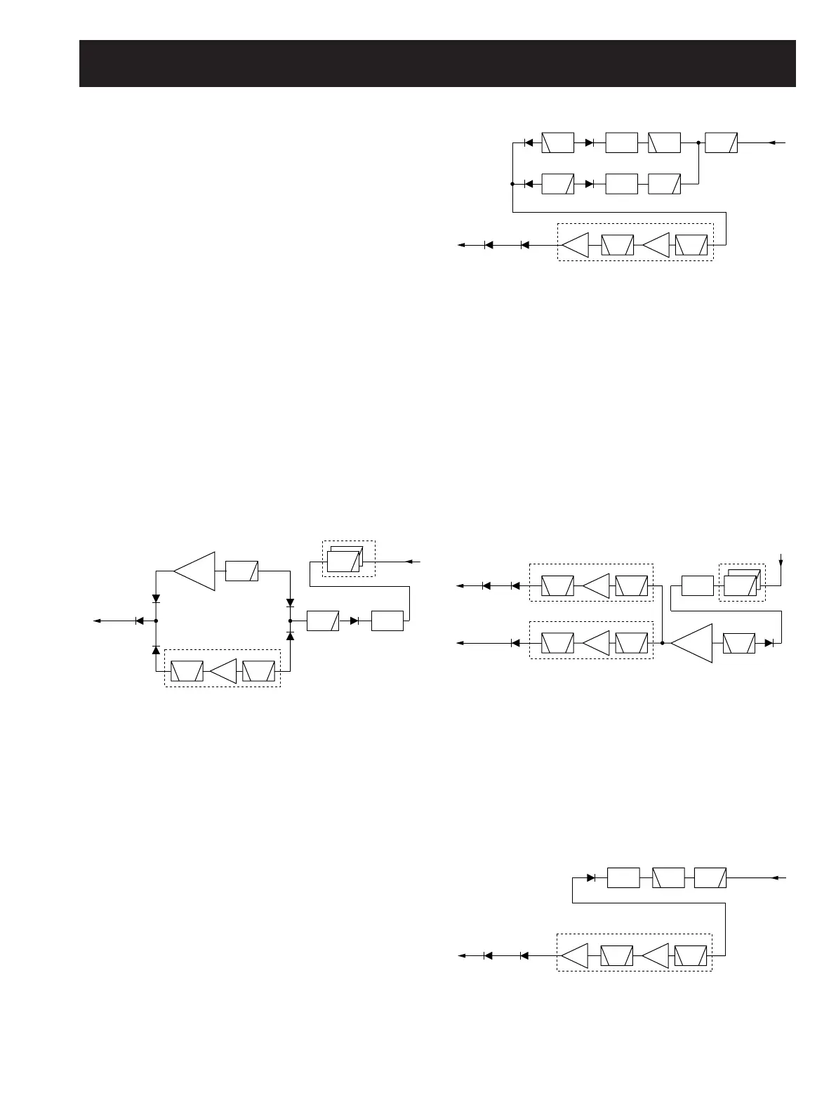
• While receiving 118–174 MHz
The 118–174 MHz band signals are passed through the two LPFs
(L1–L3, C1–C6; L5–L7, C10–C14) and attenuator (D10), then
applied to the RF amplifier (Q400) via the band switch (D400) and
bandpass filter (BPF; L400, L405, C400, C401).
The amplified signals are applied to the tuned RF amplifiers for A_
BAND (Q401, D401–D403) and B_BAND (Q450, D450–D452).
The amplified signals by Q401 are then applied to the A_BAND
1st mixer (IC900, pin 1) via the band switches (D405, D509).
The amplified signals by Q450 are then applied to the B_BAND
1st mixer (MAIN UNIT; IC50, pin 1) via the band switch (D454) and
J1001 (pin 15).
- 118–174 MHz -
• While receiving 260–350 MHz or 470–600 MHz
The 260–350 MHz and 470–600 MHz band signals passed through
the LPF (L1–L3, C1–C6) and HPF (L4, C7–C9), then applied to
the tuned RF amplifier (Q500, Q501, D502, D505, D506) via the
attenuator (D7) and band switch (D500).
The amplified signals are applied to the A_BAND 1st mixer (IC900,
pin 1) via the band switches (D508, D509).
- 260–350 MHz or 470–600 MHz -