4 - 6
4-3 FREQUENCY SYNTHESIZER CIRCUITS
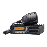
VCOs
A VCO is an oscillator which its oscillation frequency is
determined by the applied voltage. This transceiver has
two VCOs; RX VCO and TX VCO. The RX VCO generates
the 1st LO signals for the 1st IF produce, and TX VCO
generates TX signal. The VCO SW toggles these VCOs.
• RX VCO
The RX VCO oscillates 89.65 to 127.65 MHz LO signals.
The generated 1st LO signals are applied to the 1st mixer
(Q3) via two buffers (Q12 and Q10) and LPF.
• TX VCO
The TX VCO oscillates 136 to 174 MHz TX signal. The
generated TX signal is applied to the pre-driver (one of TX
AMPs) via the TX/RX SW.
A portion of the VCO output is applied to the PLL IC via the
buffer (Q11).
C126
R65
C107
R87
R59
C99
0.001
C93
TX
C129
C190
C122
L21
C195
C110
L41
C103
Q9
L42
L27
Q12
R82
C191
C127
R72
C113
D1 6
C194
R61
D21
L38
C193
C118
C148
C95
1stLO
To PLL
R8 4
C102
R71
C124
C108
0.01
C104
R69
C114
R81
R9 8
L43
R88
L26
R67
R63
D17
EP1
R76
Q15
1
2
34
5
Q11
C137
C205
R62
L19
L25
C106
R7 5
C105
C117
D15
C111
C120
R86
C121
Q14
D1 9
Q10
C100
LV
C109
R68
L39
R77
L24
C90
Q17
C94
D18
Q16
D14
D2 0
C133
C203
L37
R80
C96
R8 5
C116
L28
R7 9
C139
C192
C119
D22
C123
R8 3
C134
C92
C115
R78
Q13
R70
LVA
RX VCO
TX VCO
R5V
T5V
MOD
BUFFERBUFFER
BUFFER
RIPPLE
FILTER
VCO
SW
TX/RX
SW
Pre-
DRIVE
Freq.
adjust
Freq.
adjust
Modulation
L14
C324
C183
C323
C49
LPF
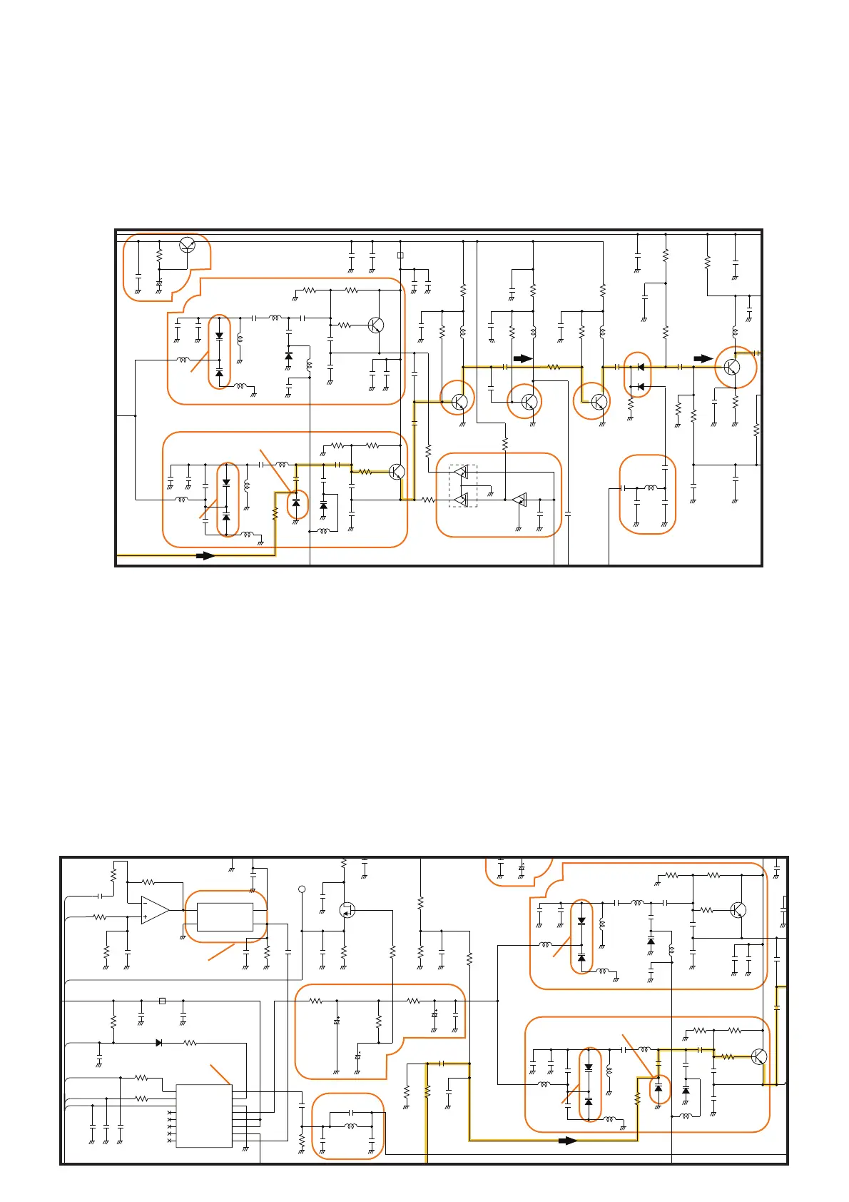
• PLL CIRCUITS
R92
C126
D24
CP1
R105
R94
R87
C129
C155
C158
C190
C122
C1
C195
R9 3
C213
L32
L42
L27
R82
from VCO
C191
Q18
C127
C113
D1 6
C194
R10
D21
47K
L38
C193
R103
C118
C141
C148
C209
R8 4
C124
C104
C153
C114
R100
R81
L43
R
L26
C152
R118
3.3 MSVA
C147
D17
R96
C143
0.001
A CZ1005Y
EP6
C1
C137
CR-783
X2
1
VCON
2
GND
3
OUT
4
VCC
C211
L25
R109
C117
C120
R86
C157
C121
R9 5
Q14
D1 9
C149
R97
LV
E
L39
L24
R90
C146
R110
C151
C140
D18
C156
D2 0
C133
C203
L37
R8 5
C116
L28
R7 9
C150
R187
C138
C154
C192
C119
D22
R108
R104
C123
R8 3
IC16
2
3
1
R117
C132
C134
C115
R9 1
R89
C208
C207
C145
C206
MB15A02PFV1
IC4
1
OSCIN
2
OSCOUT
3
VP
4
VCC
5
DO
6
GND
7
LD
8
FIN
9
CLOCK
10
DATA
11
LE
12
FC
13
NC
14
FOUT
15
P
16
B
Q13
BAL
REF
PLST
SCK
SO
LVA
UNLK
LVIN
RX VCO
TX VCO
PLL
S5V
MOD
LOOP
FILTER
LPF
PLL IC
Ref. Freq.
OSCILLATOR
Freq.
adjust
Freq.
adjust
Modulation
PLL (Phase Locked Loop) CIRCUIT
The PLL circuit provides stable oscillation for both of the
transmit and 1st LO frequencies (for receive). By comparing
the feed backed VCO output and the reference frequency
signal, the oscillating frequency is stabilized.
The PLL output frequency is controlled by the serial data
including divide ratio from the CPU.
A portion of VCO output from the buffer (Q11) is applied
to the PLL IC via LPF. The applied VCO output is divided
according to the serial data including divide ratio from
the CPU, at the prescaler and programmable divider. In
the same way, the reference frequency signal from the
reference frequency signal oscillator is applied to the PLL
IC and divide so that these are the same frequency.
The frequency-matched signals are applied to the phase
comparator and phase-compared. The resulted phase
difference is detected as a phase-type signal, and level-
adjusted at the charge pump then output. The output pulse
type signal is passed through the loop filter to be converted
into the DC voltage (=Lock Voltage).
Applying the lock voltage to the variable capacitors
(VD) which composes a part of the resonator of VCO,
the capasitance of VDs changes corresponding to the
applied lock voltage. This causes the change of resonation
frequency that determines the VCO oscillating frequency to
keep the VCO frequency constant.
When the oscillation frequency drifts, its phase changes
from that of the reference frequency, causing a lock voltage
change to compensate for the drift in the VCO oscillating
frequency.
• VCOs AND BUFFERS

 Loading...