4 - 1
SECTION 4 CIRCUIT DESCRIPTION
While transmitting, serial-connected PIN diodes are ON,
thus the TX line is connected to the antenna, and the RX
line is connected to the GND simultaneously to prevent TX
signal entering.
The limitter protects RX line from over-level RF inputs, and
the BEF (=trap) damps unwanted signals to GND.
The tuned-BPF is adjusted so that it responds to receiving
frequency and rejects all others, by the variable capacitor
whose capacitance is varied by added voltage "T1" and "T2."
The RF AMP amplifi es RX signals to a level suited to the 1st
mixer.
4-1 RECEIVER CIRCUITS
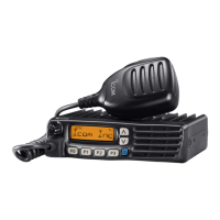
RF CIRCUITS
RF circuits consist of RF fi lters, antenna switch (ANT SW),
RF amplifi er (RF AMP), etc., and extracts and amplifi es the
signals of frequency which desired to receive.
The received signals (RX signals) from the antenna are passed
through the LPF, ANT SW (as an LPF in RX), limitter , BEF
(Band Eliminate Filter) and the two-staged tuned BPF. The
fi ltered RX signals are amplifi ed by the RF AMP, and passed
through another two-staged tuned BPF. The fi ltered RX signals
are then applied to the 1st IF circuits.
The ANT SW toggles RX line and TX line. While receiving,
the TX line and the antenna is disconnected to prevent RX
signals entering. The RX line is disconnected from the GND
simultaneously, and an LPF which guides received signals
to the RX circuits is composed.
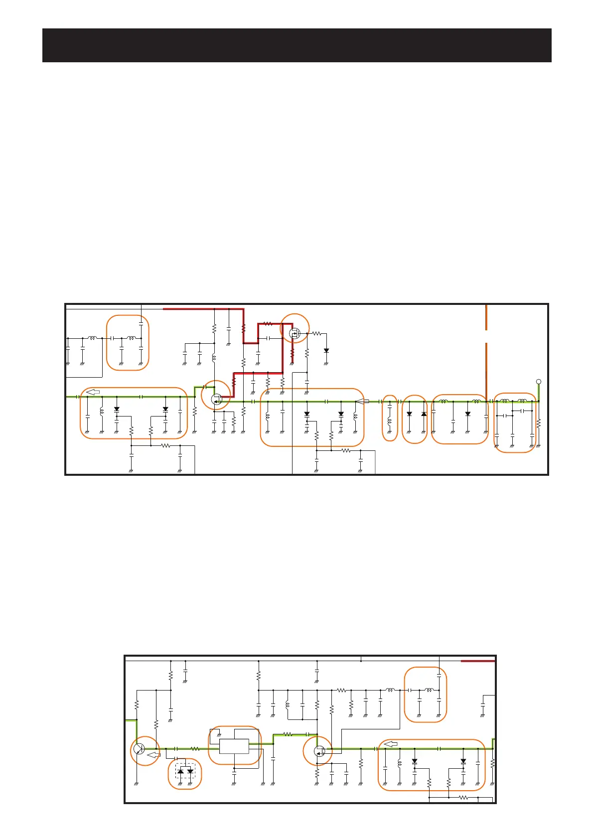
1ST IF CIRCUITS
The 1st IF circuits consist of 1st mixer, 1st IF fi lter and 1st IF
amplifi er (IF AMP). And it converts the RX signals into the
1st IF signal, then filters to remove unwanted signals and
amplifi es.
The filtered RX signals are applied to the 1st mixer to be
converted into the 1st IF signal, by being mixed with the 1st
Local Oscillator (LO) signals “1stLO” from the RX VCO via
the LPF.
C55
D10
L13
C60
FL-335
FI1
1
IN
2
OU T
3
GND
4
GND
56
R30
R48
1stIF
R25
Q3
L14
C54
Q4
C322
D9
R34
C56
C5 8
C4 1
C5 1
1
R31
R20
C39
C53
C324
C36
C44
C52
R3 3
R23
L11
R29
R21
C48
C35
L1
1stLO
2
C183
C321
C323
R26
R35
R32
C57
C50
R28
C59
C329
R2 7
C45
C38
C40
D26
C49
R5V R5V
R5V
LPF
LIMITTER
1st IF
AMP
1st
MIXER
Two-staged
1st IF
FILETR
C14
D10
C26
C186
R11
L14
R12
R172
C42
6P
C25
R15
R18
R13
C322
D9
R2 2
C28
C27
C4 1
L5
C2 2
R20
C39
D23
C324
C36
C44
L6
D6
L31
C19
C23
C43
C17
Q2
R23
C37
L11
D8
R21
R171
Q1
L7
C20
R19
R174
L9
C29
C35
L1
1stLO
2
C183
R173
C24
C184
C32
R213
C323
C16
R14
C18
C33
R175
D5
L8
R16
C31
R17
D4
C30
C45
C38
D7
C40
C49
T2
T1
RSSI
R5V
BEF
LPF
LPF (ANT SW)
LPF
LIMITTER
RF
AMP
AGC LINE
DRIVER
Two-staged
TUNED BPF
Two-staged
TUNED BPF
C2
To ANT
L2
L1C6
C5
C1
R51
C4
C3
To TX AMP
The converted 1st IF signal is passed through the 1st IF fi lter
to be removed unwanted signals. The fi ltered 1st IF signal is
applied to the 1st IF AMP via the limitter. The amplifi ed 1st
IF signal is then applied to the 2nd IF circuits.
• RF CIRCUITS
• 1ST IF CIRCUITS

 Loading...