3 - 1
SECTION 3 DISASSEMBLY INSTRUCTION
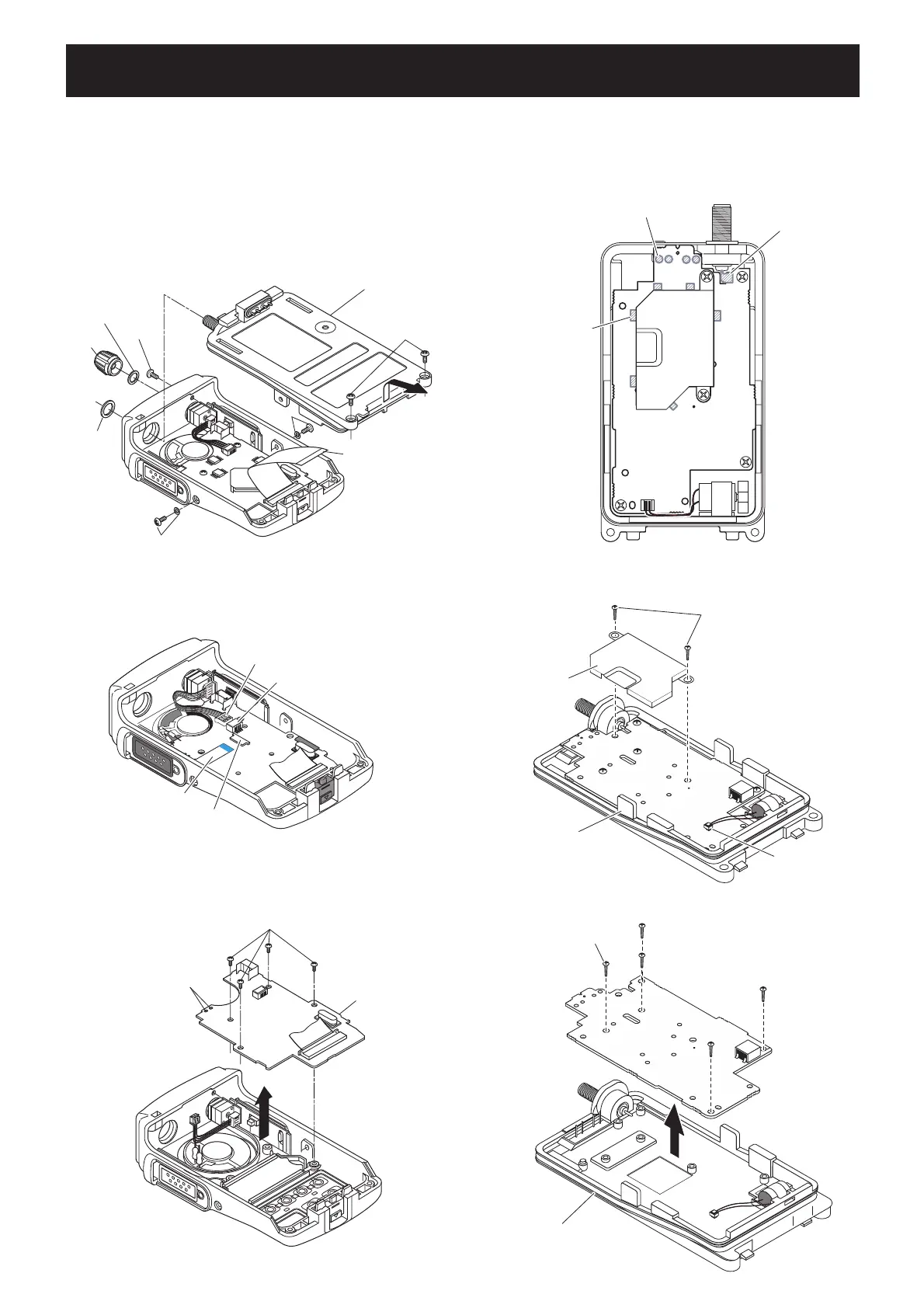
1. REMOVING THE CHASSIS UNIT
q Unscrew the ANT nut, and remove the VR knob.
w Remove the VR washer, and unscrew the top screw.
e Unscrew side screws and washers.
r Unscrew bottom screws.
t Take off the CHASSIS UNIT in the direction of the
arrow.
y Disconnect the flat cable from the CHASSIS UNIT
(MAIN UNIT).
2. REMOVING THE FRONT UNIT
q Disconnect the VR cable from J402.
w Disconnect the flat cable from J403.
3. REMOVING THE MAIN UNIT
q Unsolder 6 points from the shield cover.
w Unsolder 4 points from the contact spring.
e Unsolder 1 point from the antenna connector.
Unsolder ×6
(shield cover)
Unsolder ×4
(contact spring)
Unsolder ×1
(antenna connector)
MAIN UNIT
CHASSIS
VR knob
ANT nut
Flat cable
VR washer
Top screw
Side screw & Washer
Bottom screws
Side screw & washer
r Unscrew 2 screws, and remove the shield cover.
t
Disconnect the motor connector* from the MAIN UNIT.
Shield cover
Unscrew ×2
Disconnect
(motor connector)
CHASSIS
MAIN UNIT
Unscrew ×5
CHASSIS
MAIN UNIT
y Unscrew 5 screws, and take off the MAIN UNIT.
VR cable
Flat cable
J403
J402
e Unscrew 4 screws.
r Unsolder 2 points (at the speaker leads).
t Take off the FRONT UNIT in the direction of the
arrow.
FRONT UNIT
Unscrew ×4
Unsolder ×2
(Speaker leads)
*
*: Except [A], [D], [G], [J]

 Loading...