■Mounting the transceiver
The front panel can be inverted for correct viewing while
leaving the built-in speaker facing away from the mounting
surface.
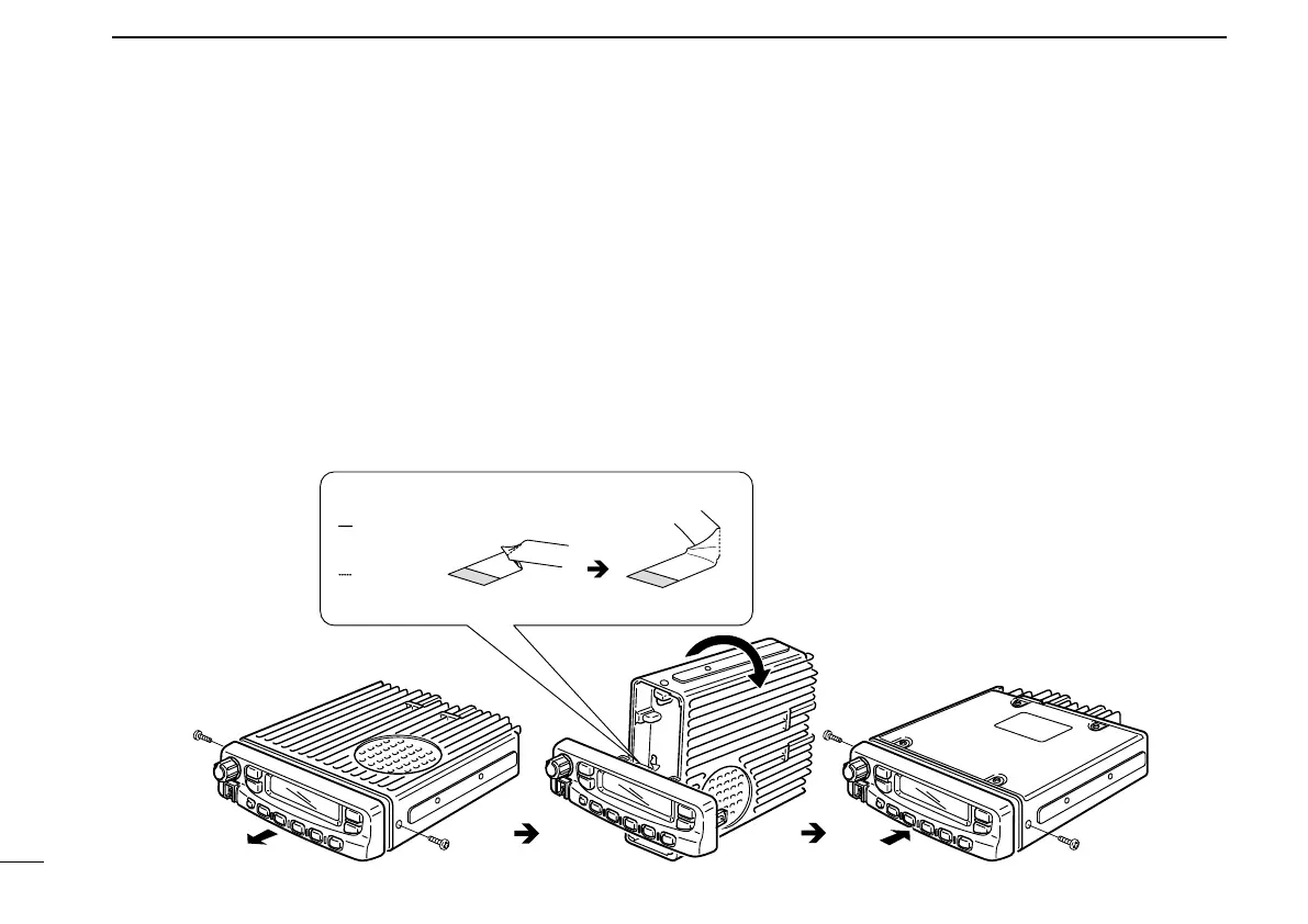
D Inverting the Front panel
q Unscrew the 2-side screws.
w Detach the Front panel forward from the transceiver.
e Bend the flat cable between Front panel and main unit as
shown in the following diagram.
r Invert the transceiver 180 degrees clockwise as below.
t Re-attach the Front panel to the transceiver.
y Tighten the 2 screws.
CAUTION:
• NEVER rotate the transceiver more than 180 degrees.
• DO NOT bend the flat cable too hard. Damage may occur.
normal bend line
inverted
bend line
Flat cable orientation
to Front panel
to MAIN unit
NOTE: Be sure to bend the flat cable in the
correct direction, before turning over
(inverting) the transceiver.
13
3
CONNECTION AND MAINTENANCE

 Loading...