2001 NEW
75
6
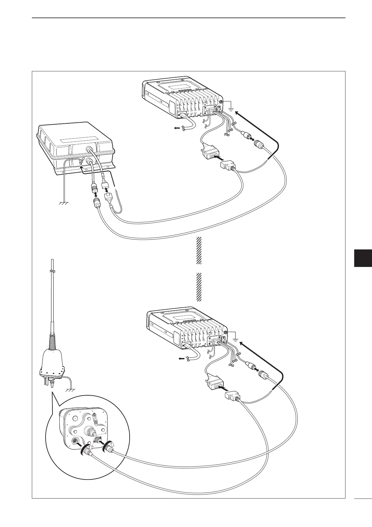
CONNECTION AND INSTALLATION
1
2
3
4
5
6
7
8
9
10
11
12
13
14
15
16
17
Quick Reference
AT-140
AH-740
Ground
IC-F8101 main unit
to a 13.8 V
DC power source
to [ATU]
Ground
(see page 76)
Ground
(see page 76)
D-sub 9 pin
(female)
Ground
IC-F8101 main unit
to a 13.8 V
DC power source
to [ATU]
D-sub 9 pin
(female)
DO NOT pull the antenna and control cable re-
ceptacles. This may cause a cable disconnection
(in the tuner unit), inside connector damage or a
bad connection.
Wrap both the antenna and the control cable con-
nectors with rubber vulcanizing tape, and then
wrap electrical tape over the rubber vulcanizing
tape to help in waterproofing.
Coaxial cable
(User supplied)
Both cables are supplied
with the AH-740.
Coaxial cable
(6 m; 19.7 ft)
OPC-2309
(10 m; 32.8 ft): 4 pin
Control cable
(6 m; 19.7 ft)
 Loading...