2001 NEW
79
6
CONNECTION AND INSTALLATION
1
2
3
4
5
6
7
8
9
10
11
12
13
14
15
16
17
Quick Reference
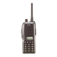
t Unscrew the 4 rear plate screws, then remove the
rear plates from both the front panel and Main unit
attachments.
Rear plate
*This illustration
shows the descrip-
tion for the Main
unit attachment.
Main unit attachment
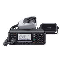
y Connect either the OPC-607, OPC-608, OPC-609
or OPC-726 separation cable to the Main unit at-
tachment, as shown below.
After connecting the cable, replace the rear plate
and the 4 screws.
• The separation cable can be inserted into either the left or
right grooves on the back of the attachment.
Use the supplied
screw (M3 × 8 mm).
Rear plate
Main unit attachment
Cable groove
Separation cable
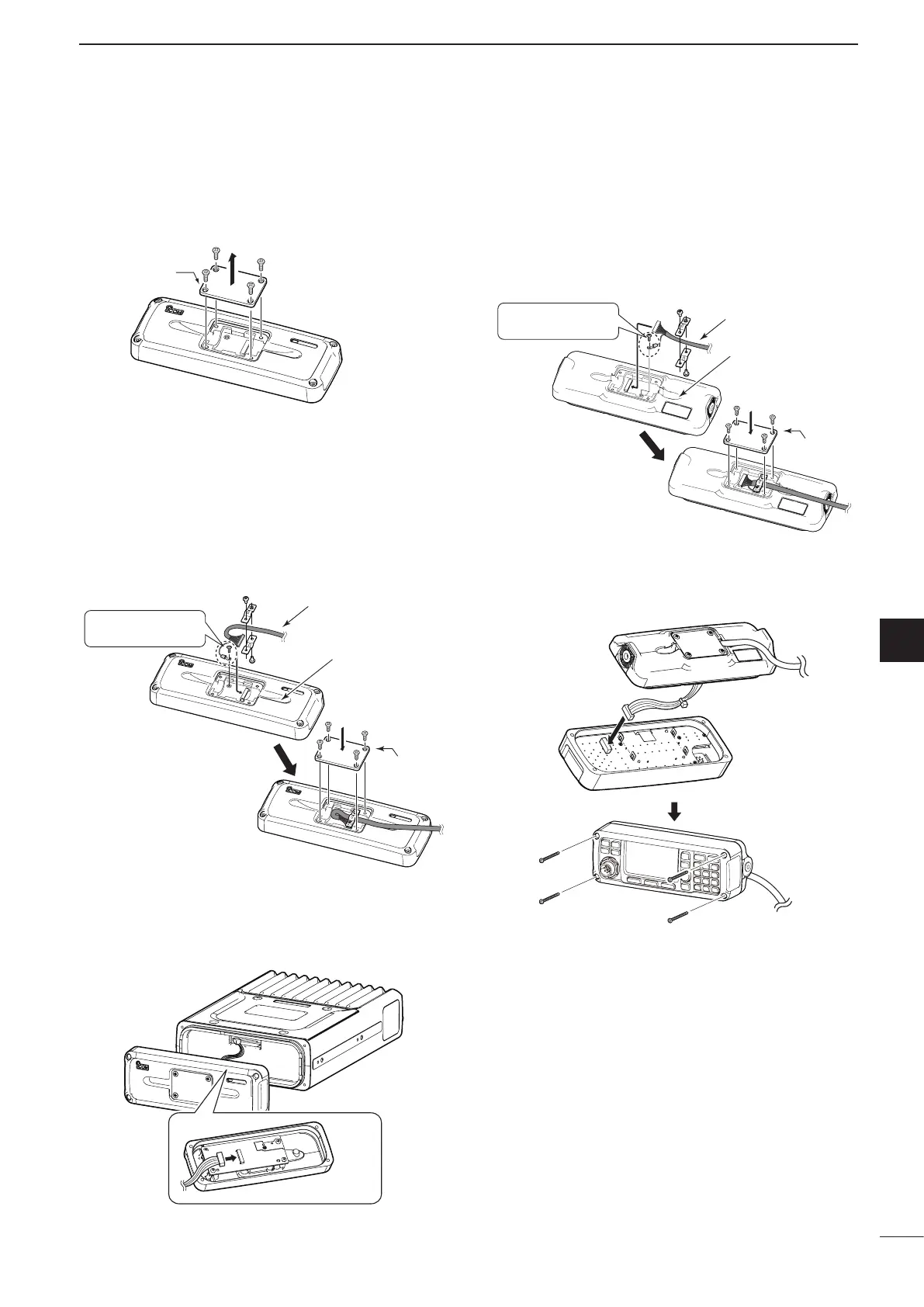
u Connect the connection cable coming from the
RMK-6, as shown below.
Then tighten the 4 hex socket screws.
i Connect the other end of the Separation cable to
the front panel attachment, as shown below.
After the cable connection, replace the removed
rear plate and the 4 screws.
• The separation cable can be inserted into either the left or
right grooves on the back of the attachment.
Rear plate
Front panel attachment
Cable groove
Separation cable
Use the supplied
screw (M3 × 8 mm).
o Connect the connection cable coming from the
RMK-6, as shown below.
Then tighten the 4 hex socket screws.
 Loading...