3- 1
SECTION 3 DISASSEMBLY AND OPTION INSTRUCTIONS
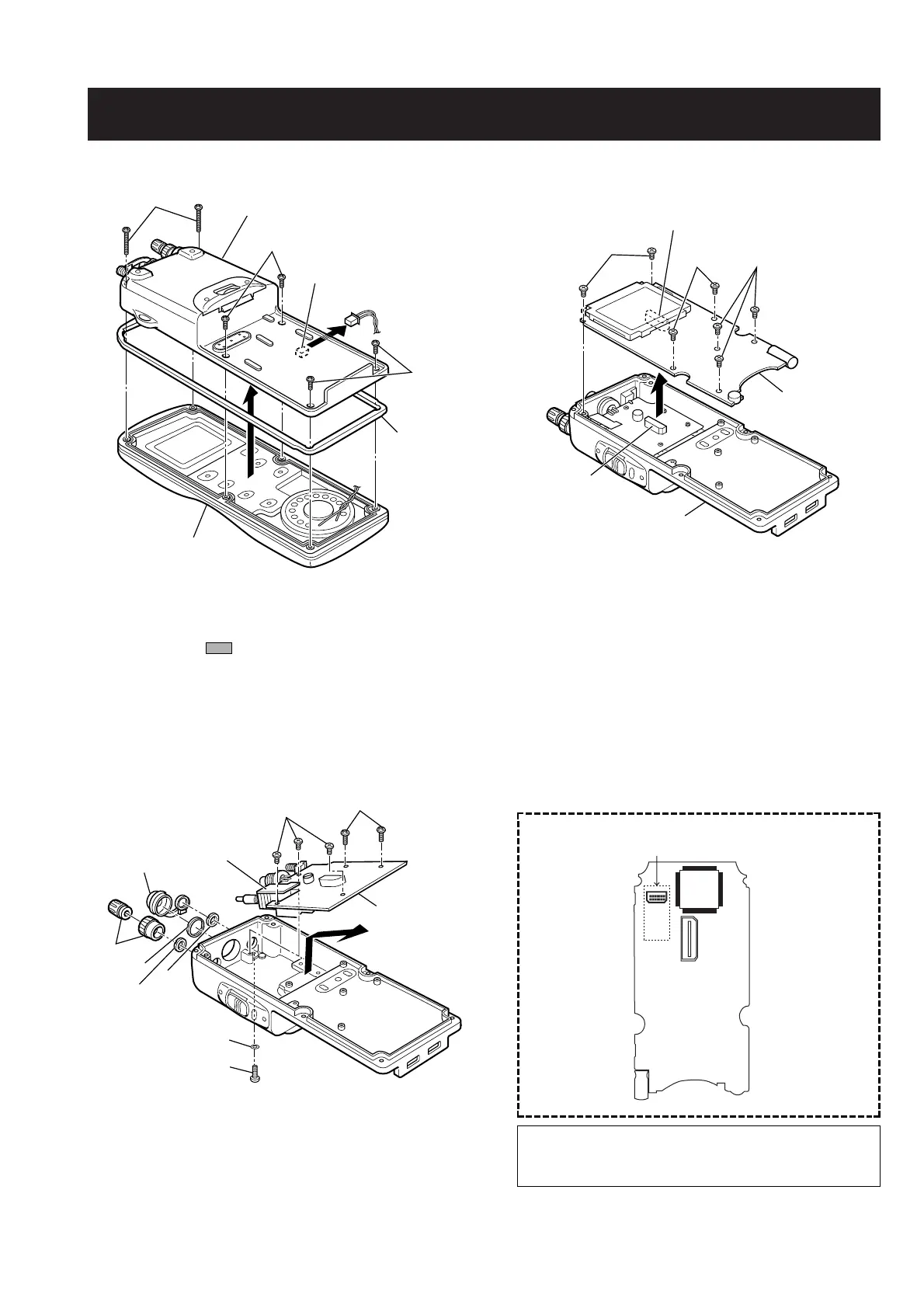
• Removing the Rear panel • Removing the MAIN unit
• Removing the RF unit • Install the optional unit (UT-98 or UT-112) to the
connector (MAIN unit ; J3)
Unscrew 2 screws
A
(2 × 20 mm), and 4 screws
B
(2 × 5 mm, black) from the rear panel.
q Unscrew 7 screws
C
(2 × 3.5 mm, silver) from
the MAIN unit.
w Unplug J1 to separate the rear panel and the
MAIN unit.
q Remove connector cap.
w Remove 2 knobs, and unscrew 3 nuts (
F
,
G
,
H
)
e Unscrew 3 screws
D
(2 × 3.5 mm, silver), and 2 screws
E
(2 × 5 mm, black) from the RF unit.
r Unscrew 1 screw
J
(2 × 5 mm, black), and remove 1
washer
I
.
t Take off the RF unit in the direction of the arrow.
NOTE : Once the front panel is removed, grease must be
applied to areas before assembly.
Manufacture : Shin-Etsu Chemical
Type : G-501
CAUTION :
DO NOT guarantee the waterproof construction when
installing the optional unit except distributors or dealers.
 Loading...