4 - 4
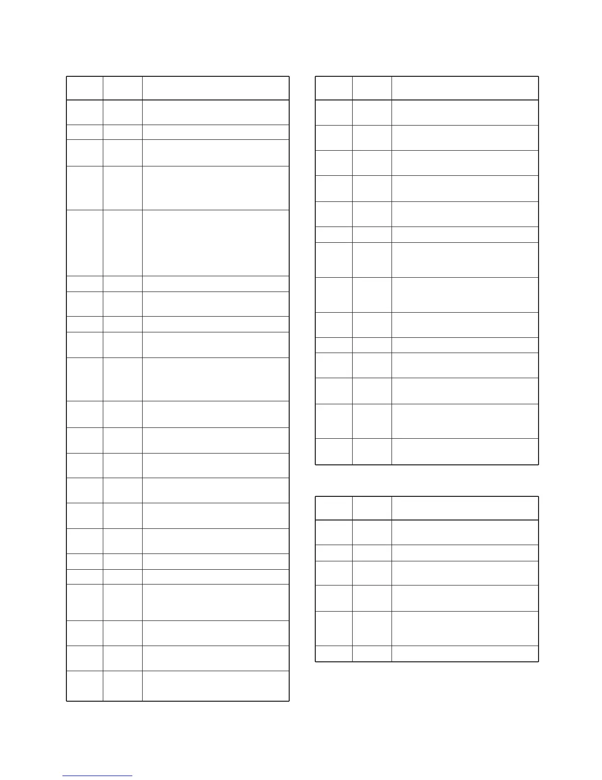
4-5 PORT ALLOCATIONS
4-5-1 CPU (IC360)
Pin
number
1
2
3
5
7
8
16
17
18
19
20
21
23
24
25
26
27
28
29
30
51
52
53
Port
name
LCDC1
LCDC2
BEEP
UNLK
BTYPE
BPFS
SCK
PLST
SDATA
DAST
LEDK
LEDL
ESDA
V5VS
T5VS
R5VS
AFVS
CLIN
CLOUT
IVOLM
HL
SQL
UP
Description
Outputs LCD contrast control signal.
Outputs beep audio signals.
Input port for unlock signal.
High : PLL is unlocked.
Input port for battery’s type and
cloning cable connecting detection.
Low : While alkaline cell battery is
used in the battery case.
Outputs RF band-pass filters control
signal.
High : While receiving below
159.990 MHz.
Low : While receiving above
160.000 MHz.
Outputs serial clock.
Outputs strobe signal to the PLL IC
(IC1, pin 3).
Outputs serial data.
Outputs strobe signal to the D/A con-
vertor IC (IC190, pin 6).
Outputs key pad back light control sig-
nal.
High : While key pad back light is
ON.
Outputs LCD back light control signal.
High : While LCD back light is ON.
I/O port for the EEPROM (IC340, pin
5) serial data signals.
Outputs the V5 regulator control sig-
nal.
Outputs the T5 regulator control sig-
nal.
Outputs the R5 regulator control sig-
nal.
Outputs the AF regulator control sig-
nal.
Input port for the cloning signal.
Outputs the cloning signal.
Output the speaker mute switch con-
trol signal.
High : While the AF output is muted.
Input port for the [H/L] key.
Low : While [H/L] key is pushed.
Input port for the [SQL] key.
Low : While [SQL] key is pushed.
Input port for the [
Y] key.
Low : While [Y] key is pushed.
Pin
number
54
55
56
57
58
83
84
85
86
88
91
93
94
95
Port
name
DOWN
16CH
CHWX
SCAN
DW
5VS
MICM
DETM
WET
WXTV
BATTV
TEMPV
RSSIV
PTT
Description
Input port for the [Z] key.
Low : While [Z] key is pushed.
Input port for the [16] key.
Low : While [16] key is pushed.
Input port for the [CH/WX] key.
Low : While [CH/WX] key is pushed.
Input port for the [SCN] key.
Low : While [SCN] key is pushed.
Input port for the [DW] key.
Low : While [DW] key is pushed.
Outputs 5V regulator control signal.
Outputs the MIC mute switch control
signal.
Low : While muted.
Outputs the detector mute control sig-
nal.
Low : While muted.
Input port for transceiver’s internal
inundation detection.
Input port for WX tone detection.
Input port for the battery voltage
detection.
Input port for the transceiver’s internal
temperature detection.
Input port for the RSSI signal from the
FM IF IC (IC170, pin 12) to detect
receving signal strength.
Input port for the [PTT] switch.
High : While [PTT] switch is pushed.
4-5-2 D/A converter IC (IC190)
Pin
number
2
3
10
11
14
15
Port
name
FCON
PCON
MCON
BEPO
BEPST
SQLO
Description
Output signal to adjust the reference
frequency.
Output signal to adjust TX power.
Output signal to adjust modulation
while transmitting.
Output signal to adjust beep tone level
while “AUTO” is selected in set mode.
Output signal to adjust beep tone level
while 1–10 scale is selected in set
mode.
Output signal to adjust squelch level.