EasyManuals Logo

Icom IC-M2A Service Manual

Icom IC-M2A
36 pages
To Next Page IconTo Next Page
To Previous Page IconTo Previous Page
Page #8 background imageLoading...
Page #8 background image
3 - 1
SECTION 3 DISASSEMBLY INSTRUCTIONS
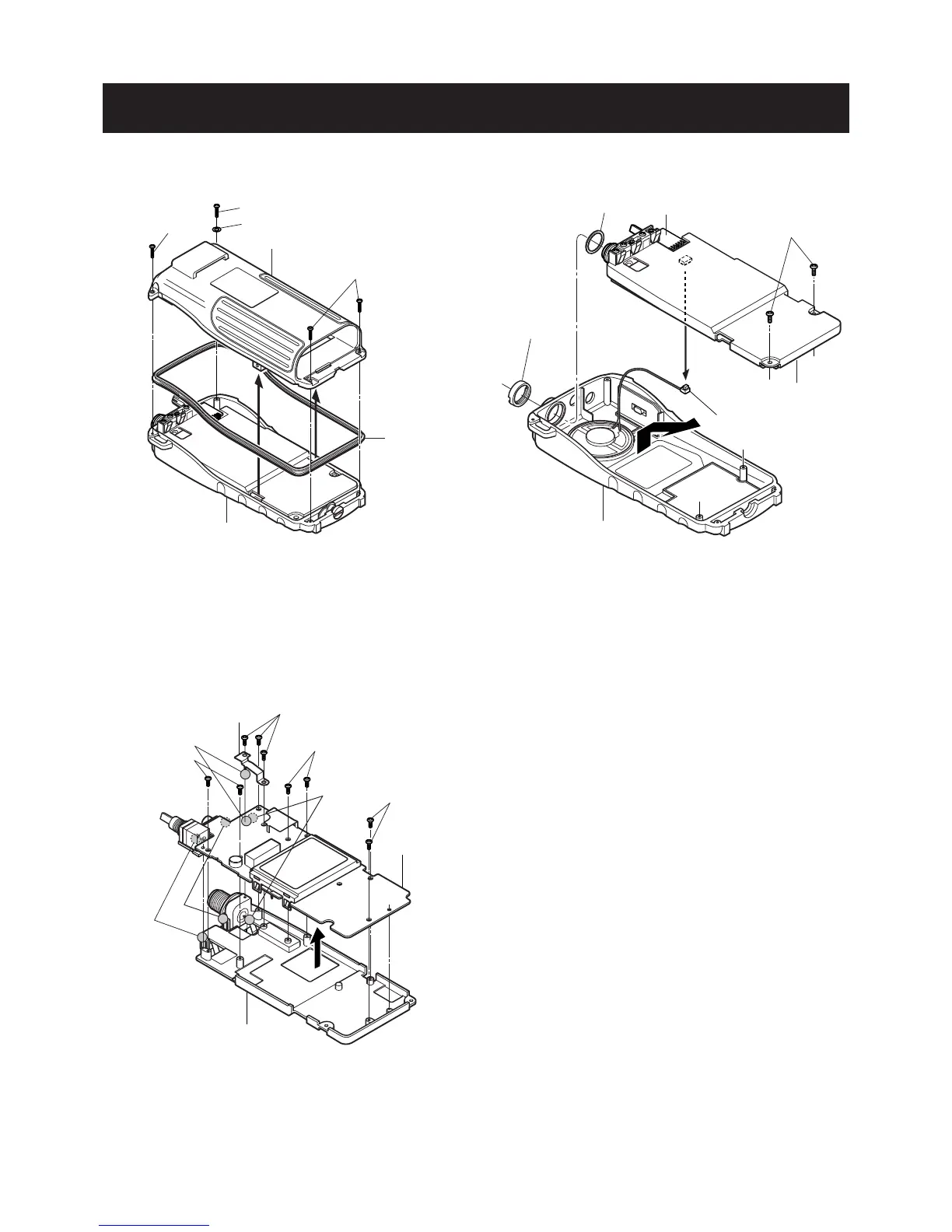
Removing the Rear panel
Removing the Chassis unit
Rear panel
A
B
C
C
Rubber
Front panel
Front panel
Chassis unit
VR unit
E
G
D
F (Speaker connector)
¡ Unscrew 1 screw, A (2 x 10 mm), and remove 1 washer, B.
Unscrew 3 screws, C (2 x 8 mm).
£ Remove the rear panel and rubber from the front panel.
¡ Unscrew 1 nut, D.
Unscrew 2 screws, E (2 x 6 mm).
£ Take off the chassis unit in the direction of the arrow.
¢ Unplug, F, to separate the front panel, J251, and the
chassis unit.
Remove 1 washer, G.
Removing the MAIN unit
¡ Unscrew 9 screws, H (2 x 4 mm).
Unsolder 4 points, I, and remove earth plate.
£ Separate the MAIN unit and the chassis.

Other manuals for Icom IC-M2A

Questions and Answers:

Question and Answer IconNeed help?

Do you have a question about the Icom IC-M2A and is the answer not in the manual?

Icom IC-M2A Specifications

General IconGeneral
BrandIcom
ModelIC-M2A
CategoryTransceiver
LanguageEnglish

Related product manuals