4 - 1
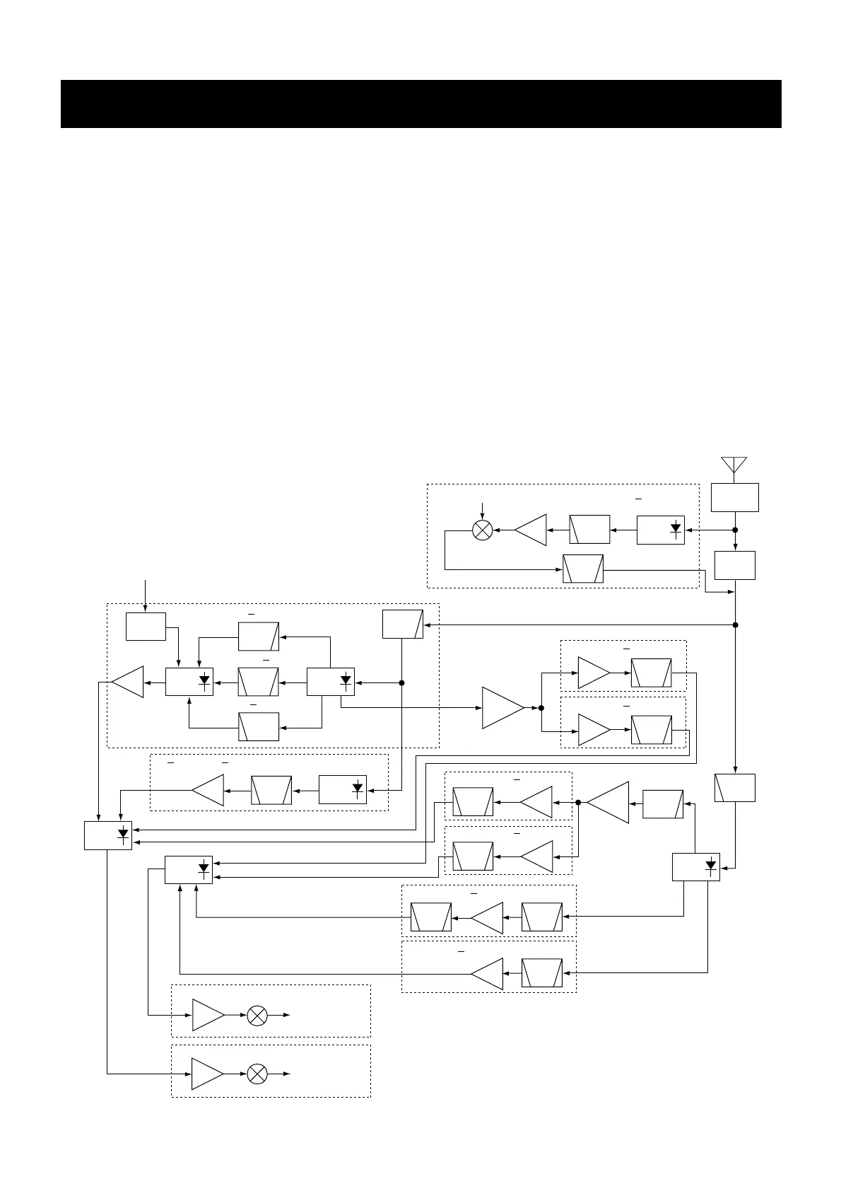
4-1 RECEIVER CIRCUITS
4-1-1 BAND SWITCHING CIRCUIT (RF UNIT)
The RF signals from the antenna connector pass through
the limiter (D68) and an attenuator* (D69). The signals are
then applied to the antenna switching circuit (D3, D11, D13,
D65, D66 and D73–D75 ).
*Above 2 GHz RF signals do not pass through the attenua-
tor.
4-1-2 RF CIRCUIT (RF UNIT)
The RF circuit amplifies the received signals within the
range of frequency coverage and filters out-of-band signals.
• A-BAND CIRCUIT
(1) MF (above 0.15 MHz, below 1.9 MHz) signals
RF signals (0.15–1.9 MHz) from an attenuator (D69) pass
through the low-pass filter (L123–L125 and C851–C853),
band switch (D66) and another low-pass filter (L88, L89,
C533–C535, C657, C658). The filtered signals pass through
another band switch (D67), and are then amplified at an RF
amplifier (Q505). The amplified signals are applied to the
next band switch (D72).
(2) HF-L (above 1.9 MHz, below 15 MHz) signals
RF signals (1.9–15 MHz) from an attenuator (D69) pass
through the low-pass filter (L123–L125 and C851–C853),
band switch (D65) and bandpass filter (L85–L87, L91,
C522–C531 and C891). The filtered signals pass through
another band switch (D70), and are then amplified at an RF
amplifier (Q505). The amplified signals are applied to the
next band switch (D72).
SECTION 4 CIRCUIT DESCRIPTION