4 - 14
4-6 BC-156 CIRCUIT DESCRIPTION
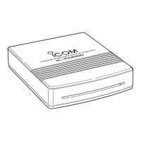
4-6-1 DC/DC CONVERTER CIRCUIT (MAIN UNIT)
Input voltage (8–16 V) from the BC-123A/E pass through
reverse protection circuit (D6) via the J1. The voltage pass
through the current limiter (R19) which can pass less than
2.0 A via the fuse (F1), and is then applied to the DC/DC
converter circuit (IC2, Q7, D2, L1 and C4). The circuit con-
verts 8–16 V input voltage to obtain approximately 5.2 V/2 A,
and the converted voltage is applied to the charging circuit
(IC1, Q1).
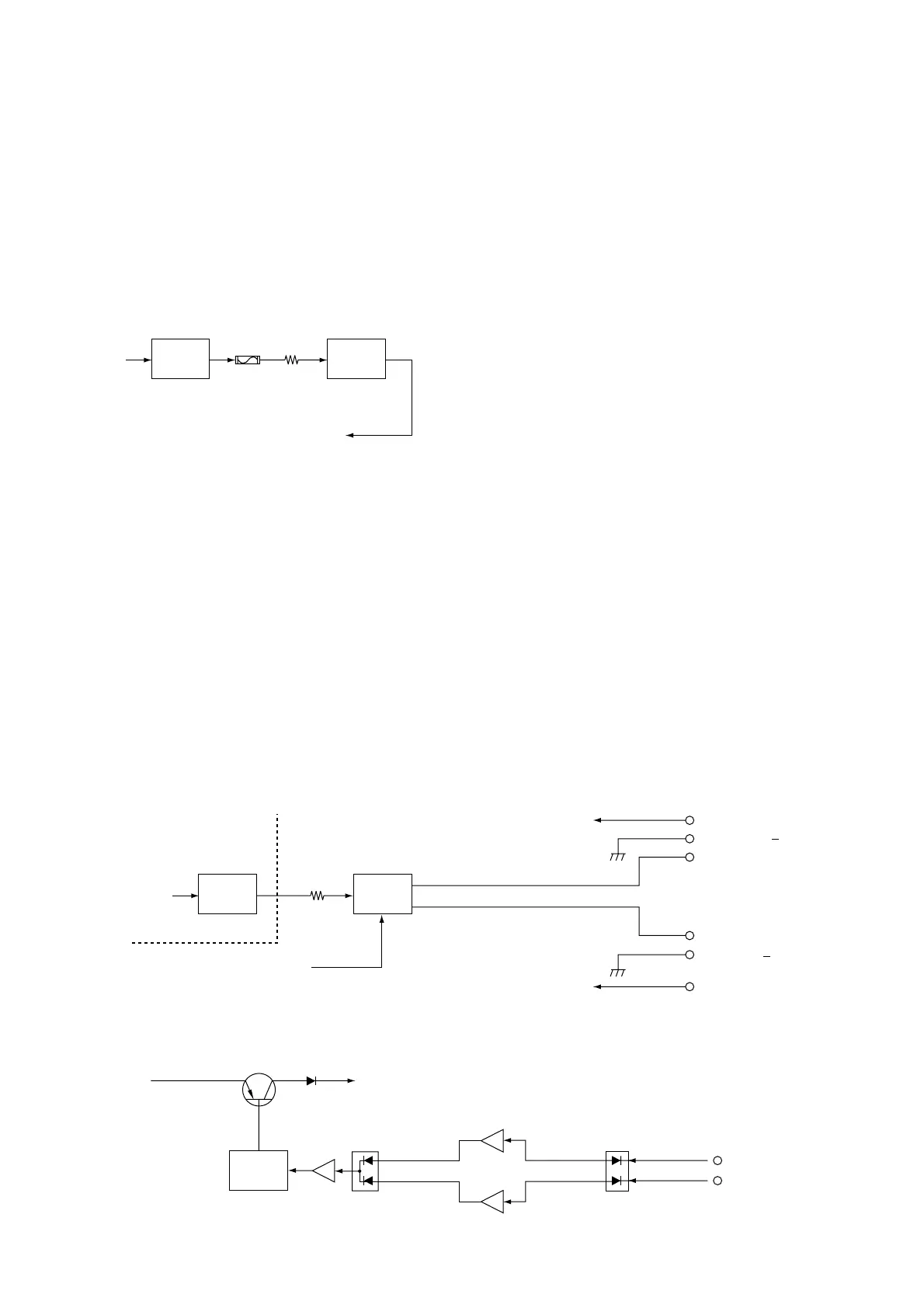
4-6-2 CHARGING CIRCUIT
(MAIN UNIT AND TANSHI BOARD)
The converted voltage from the DC/DC converter circuit is
applied to the charging circuit (MAIN unit; IC1, Q1), and is
then applied to the TANSHI board via the J4, pins 1 and 2
(MAIN unit) as “CHGOUT” signal. The signal passes
through the charging current detector (R1), and is then
applied to the charging selector (TANSHI board; RL1) which
is controlled by “CONT” signal. The signal is then applied to
the CP1 (TANSHI board) as “SBATT+” signal or CP4 as
“BATT+” signal.
A part of “CHGOUT” signal is applied to the charging circuit
(IC1, pins 13 and 14) via the J1, pin 6 (TANSHI board) to
control battery charging.
4-6-3 CHARGING CONTROL CIRCUIT
(MAIN UNIT AND TANSHI BOARD)
• CHARGING THE BATTERY WITH IC-R20
The “DET2” signal from the TANSHI board is applied to the
D5 (MAIN unit) via the J4 (MAIN unit), and is then applied to
the Q4 (MAIN unit). As Q4 turns ON, the output signal from
Q4 is applied to the D4. The signal is applied to the Q3 to
turn ON, then the output signal from Q3 is applied to the
charging control IC (MAIN unit; IC1, pin 2). The IC controls
Q1’s base voltage to keep stable voltage/current battery
charging.
A part of signal from Q4 (MAIN unit) is applied to the charg-
ing selector circuit (TANSHI board; RL1) via the J1, pin 8
(TANSHI board) as “CONT” signal.
• CHARGING THE BATTERY ONLY
The “DET1” signal from the TANSHI board is applied to the
D5 (MAIN unit) via the J4 (MAIN unit), and is then applied to
the Q2 (MAIN unit). As Q2 turns ON, the output signal from
Q2 is applied to the D4. The signal is applied to the Q3 to
turn ON, then the output signal from Q3 is applied to the
charging control IC (MAIN unit; IC1, pin 2). The IC controls
Q1’s base voltage to keep stable voltage/current battery
charging.

 Loading...