4·1·21
AGC CIRCUIT FOR FM (narrow), SSB AND
AM
MODES (IF UNIT)
In
FM
(narrow) mode, SSB mode and AM mode, a part
of
3rd IF signals from
019
are applied
to
AGC
detector
circuit
D28
to rectify 3rd IF signals. The
DC
voltage
from
D28
is DC-amplified at 018.
In
AM
mode and SSB mode,
016
turns
017
ON
and C89
is
applied
to
C91,
resulting in a longer
time
constant
than in FM (narrow) mode. The rise (attack)
time
constant
for
AGC
is
determined by
C89,
C91
and
R114,
and the fall (delay)
time
constant
is determined
by
R113.
The AGC voltage (when the IC-R7000 receives no
signal)
is
offset
by approximately 4 V by
R117
and
R116.
018
supplies IF,
RF
and MAIN UNITS
with
the AGC
signal.
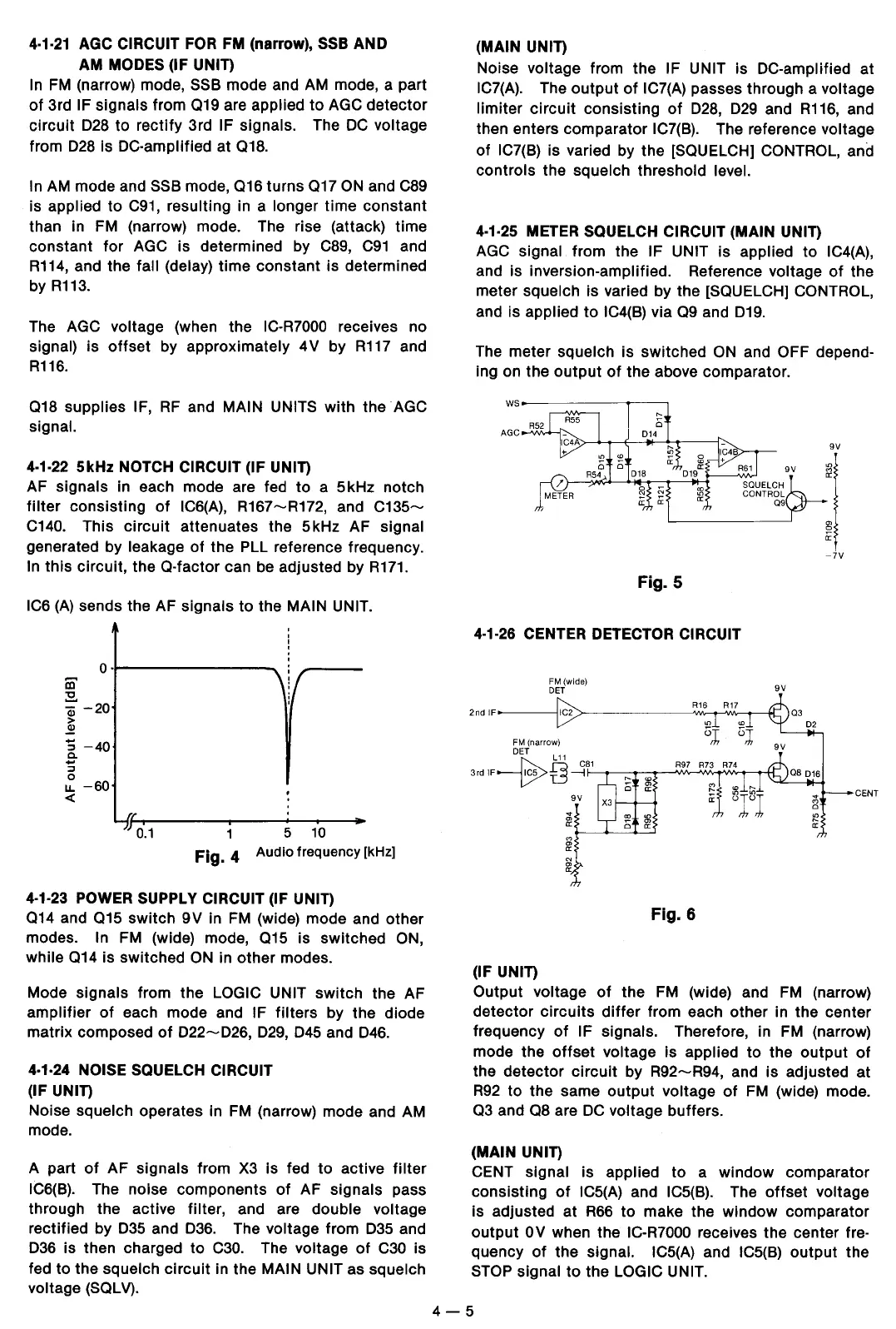
4·1·22
5kHz NOTCH CIRCUIT (IF UNIT)
AF signals in each mode are fed
to
a 5kHz notch
filter
consisting
of
IC6(A), R167-R172, and
C135-
C140. This
circuit
attenuates the
5kHz
AF signal
generated by leakage
of
the PLL reference frequency.
In
this
circuit, the
0-factor
can be adjusted by
R171.
IC6
(A)
sends the AF
signals
to
the MAIN UNIT.
o---------
to
:s!.
Qj
-20
>
~
"S
-40
.e
:l
0
u.
-60
<(
I
~
1 5
10
Fig.
4
Audio
frequency
[kHz]
4·1·23 POWER SUPPLY CIRCUIT (IF UNIT)
014
and
015
switch
9V
in
FM
(wide) mode and other
modes.
In FM (wide) mode,
015
is
switched
ON,
while
014
is switched
ON
in
other
modes.
Mode signals from the
LOGIC UNIT
switch
the AF
amplifier
of
each mode and IF
filters
by the diode
matrix composed
of
D22-D26,
029,
D45
and
D46.
4·1·24 NOISE SQUELCH CIRCUIT
(IF UNIT)
Noise squelch operates in FM (narrow) mode and AM
mode.
A part
of
AF signals from X3 is fed
to
active
filter
IC6(B). The noise
components
of
AF signals pass
through the active
filter, and are double voltage
rectified by
D35
and
D36.
The voltage from 035 and
036 is then charged
to
C30.
The voltage
of
C30 is
fed to the squelch
circuit
in the MAIN UNIT as squelch
voltage (SQLV).
(MAIN UNIT)
Noise voltage from the IF UNIT is DC-amplified at
IC7(A). The
output
of
IC7(A) passes through a voltage
limiter
circuit
consisting
of
D28,
D29
and
R116,
and
then enters comparator
IC7(B). The reference voltage
of
IC7(B) is varied by the [SQUELCH] CONTROL, and
controls
the squelch threshold level.
4·1·25
METER SQUELCH CIRCUIT (MAIN UNIT)
AGC signal from the IF UNIT
is
applied
to
IC4(A),
and is inversion-amplified. Reference voltage
of
the
meter
squelch is varied by the [SQUELCH] CONTROL,
and is applied
to
IC4(B) via
Q9
and
D19.
The meter squelch
is
switched
ON
and OFF depend-
ing on the
output
of
the above comparator.
Fig. 5
4·1·26 CENTER DETECTOR CIRCUIT
FM(wide)
DET
R16
R17
9V
2nd
IF IC2
>------_____,,,VV--.--'W'v---.----M._
(IF UNIT)
9V
'"
"'
a:
N
"'
a:
Fig. 6
-7V
CENT
Output voltage
of
the FM (wide) and
FM
(narrow)
detector
circuits
differ
from each other in the center
frequency
of
IF signals. Therefore, in FM (narrow)
mode the
offset
voltage is applied
to
the
output
of
the
detector
circuit
by
R92-R94,
and
is
adjusted
at
R92
to
the same
output
voltage
of
FM (wide) mode.
Q3
and
Q8
are
DC
voltage buffers.
(MAIN UNIT)
CENT
signal is applied
to
a
window
comparator
consisting
of
IC5(A) and IC5(B). The
offset
voltage
is adjusted at
R66
to
make the
window
comparator
output
OV
when the IC-R7000 receives the center fre-
quency
of
the signal. IC5(A) and IC5(B)
output
the
STOP signal
to
the LOGIC UNIT.
4-5
 Loading...