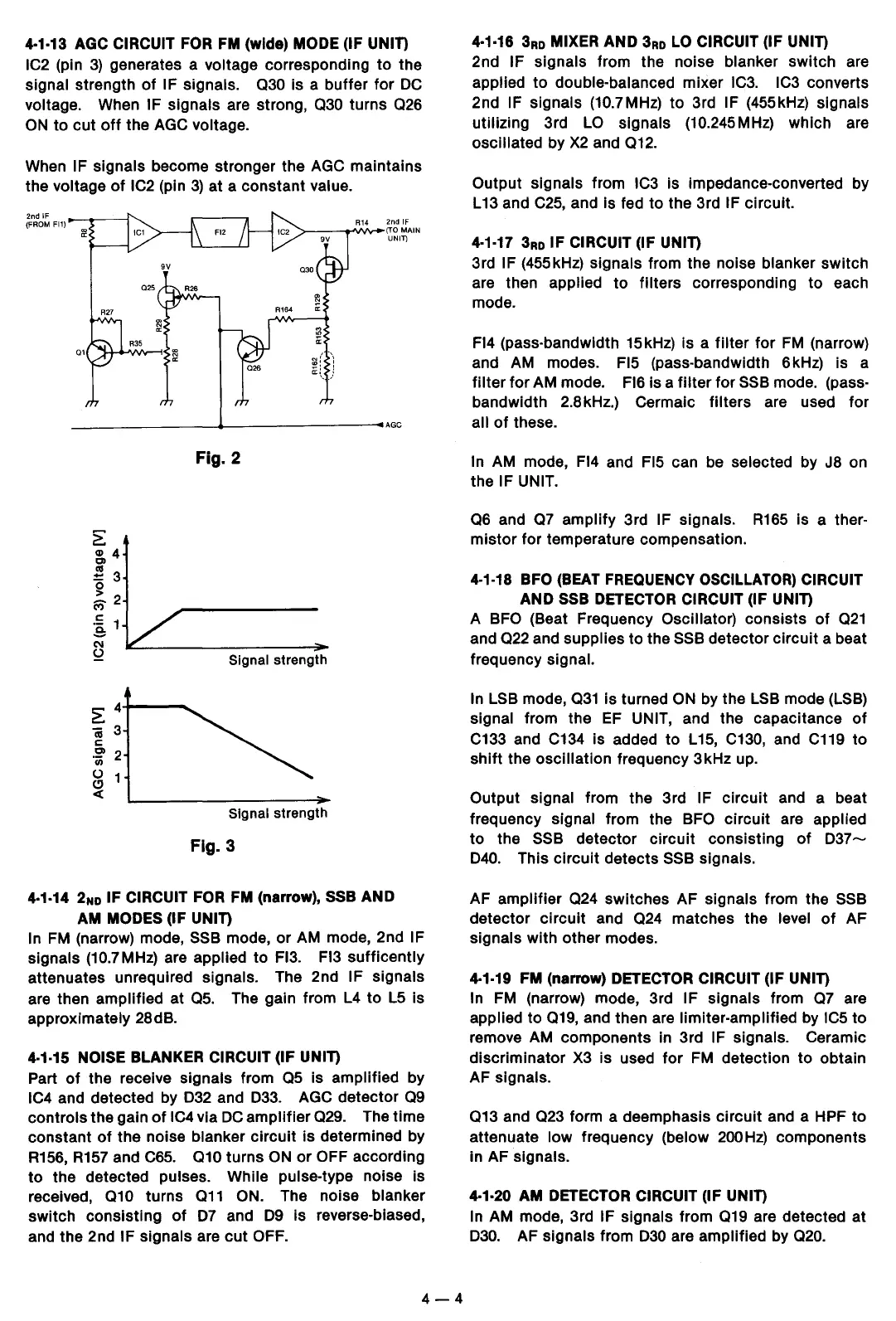
4·1-13
AGC
CIRCUIT
FOR
FM
(wide) MODE (IF UNIT)
IC2
(pin
3)
generates a voltage corresponding to the
signal strength
of
IF signals.
030
is a buffer for
DC
voltage. When IF signals are strong,
030
turns
026
ON
to cut
off
the
AGC
voltage.
When IF signals become stronger the
AGC
maintains
the
voltage
of
IC2
(pin
3)
at a constant value.
2nd
IF
(FROM Fl1)
Q1
2nd IF
>---'lfV\r-(TO
MAIN
UNIT)
--------+----------AGC
?!:
~4
~
3
0
> 2
M"
.!::
1
a
N
2
> 4
~3
c:
-~
2
()
1
(!)
c(
Fig. 2
Signal
strength
Signal
strength
Fig. 3
4·1-14
2No
IF CIRCUIT
FOR
FM
(narrow),
SSB
AND
AM
MODES (IF UNIT)
In
FM
(narrow) mode,
SSB
mode, or
AM
mode, 2nd IF
signals
(10.7
MHz)
are applied to Fl3. Fl3 sufficently
attenuates unrequired signals. The 2nd
IF signals
are then amplified at 05. The gain from
L4
to
L5
is
approximately 28dB.
4·1-15
NOISE BLANKER CIRCUIT (IF UNIT)
Part
of
the receive signals from
05
is amplified by
IC4
and detected by
D32
and
D33.
AGC
detector
09
controls the gain
of
IC4
via
DC
amplifier 029. The time
constant
of
the noise blanker circuit is determined by
R156,
R157
and
C65.
010
turns
ON
or
OFF according
to
the detected pulses. While pulse-type noise is
received,
010
turns 011 ON. The noise blanker
switch consisting
of
D7
and
D9
is reverse-biased,
and the 2nd
IF signals are
cut
OFF.
4-4
4·1-16
3Ro
MIXER AND
3Ro
LO
CIRCUIT (IF UNIT)
2nd IF signals from the noise blanker switch are
applied to double-balanced mixer
IC3.
IC3
converts
2nd
IF signals (10.7MHz) to 3rd IF (455kHz) signals
utilizing
3rd
LO
signals
(10.245
MHz)
which are
oscillated by
X2
and 012.
Output signals from
IC3
is impedance-converted by
L
13
and
C25,
and is fed to the 3rd IF circuit.
4·1-17
3Ro
IF CIRCUIT (IF UNIT)
3rd IF (455kHz) signals from the noise blanker switch
are then
applied to filters corresponding to each
mode.
Fl4 (pass-bandwidth 15kHz) is a
filter
for
FM
(narrow)
and
AM
modes. Fl5 (pass-bandwidth 6kHz) is a
filter for
AM
mode. Fl6 is a
filter
for
SSB
mode. (pass-
bandwidth 2.8kHz.) Cermaic filters are used for
all
of
these.
In
AM
mode, Fl4 and Fl5 can be selected by
JS
on
the
IF UNIT.
06
and
07
amplify 3rd IF signals.
R165
is a ther-
mistor for temperature compensation.
4-1-18
BFO
(BEAT
FREQUENCY
OSCILLATOR)
CIRCUIT
AND
SSB
DETECTOR
CIRCUIT (IF UNIT)
A
BFO
(Beat Frequency Oscillator) consists
of
021
and
022
and supplies
to
the
SSB
detector circuit a beat
frequency
signal.
In
LSB mode, 031 is turned
ON
by the LSB mode
(LSB)
signal from the
EF
UNIT, and the capacitance
of
C133
and
C134
is added
to
L15,
C130,
and
C119
to
shift
the oscillation frequency 3kHz up.
Output signal from the 3rd
IF circuit and a beat
frequency
signal from the BFO circuit are applied
to the SSB detector circuit consisting
of
D37-
D40.
This circuit detects
SSB
signals.
AF amplifier
024
switches AF signals from the
SSB
detector circuit and 024 matches the level
of
AF
signals with other modes.
4·1·19
FM
(narrow)
DETECTOR
CIRCUIT (IF UNIT)
In
FM
(narrow) mode, 3rd IF signals from
07
are
applied to 019, and then are limiter-amplified by IC5 to
remove
AM
components in 3rd IF signals. Ceramic
discriminator
X3
is used
for
FM
detection to obtain
AF signals.
013
and
023
form a deemphasis circuit and a HPF to
attenuate low frequency (below
200
Hz)
components
in AF signals.
4·1·20
AM
DETECTOR
CIRCUIT (IF UNIT)
In
AM
mode, 3rd IF signals from
019
are detected at
D30.
AF signals from
D30
are amplified by 020.
 Loading...