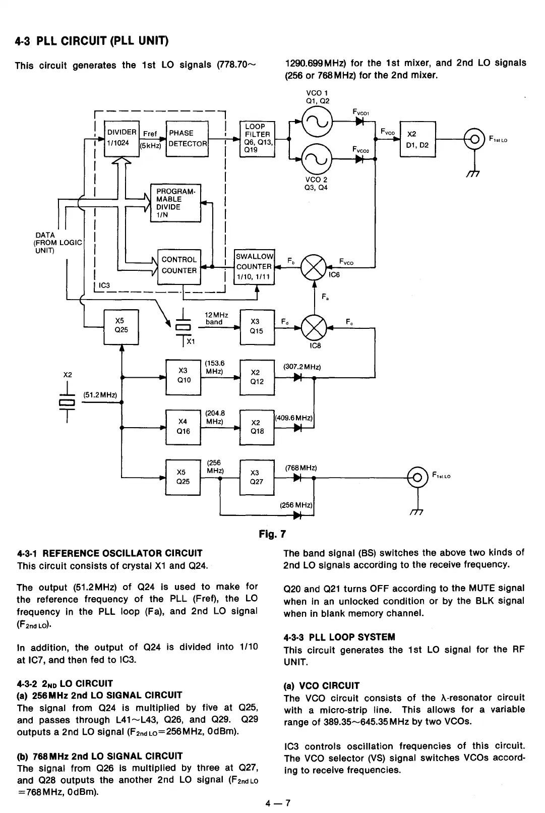
4.3 PLL CIRCUIT (PLL UNIT)
This
circuit
generates the
1st
LO
signals
(778.70-
DATA
(FROM LOGIC
UNIT)
,----------,
I DIVIDER Fret PHASE I
I
I
I
I
1/1024 (5kHz) DETECTOR
PROGRAM·
MABLE
DIVIDE
1/N
LOOP
FILTER
06,
013,
019
I
'---HI
CONTROL
I
COUNTER
-~.,-1
COUNTER
1/10,1/11
~:__
_________
_J
X2
J_
X5
025
(51.2MHz)
c::::i
___
...
T
J_
c::::J
Tx1
X3
010
X4
016
XS
025
12MHz
band
(153.6
MHz)
(204.8
MHz)
(256
MHz)
X3
015
X2
012
X2
018
X3
027
1290.699MHz)
for
the
1st
mixer, and 2nd
LO
signals
(256
or
768
MHz)
for
the 2nd mixer.
vco
1
01,
02
vco 2
03,
04
IC8
(307.2MHz)
(409.6MHz)
(768MHz)
(256
MHz)
Fvco
X2
D1,
D2
Fvco
Fe
F1stLo
Fig. 7
4·3·1
REFERENCE OSCILLATOR CIRCUIT
This
circuit
consists
of
crystal
X1
and 024.
The
output
(51.2MHz)
of
Q24 is used
to
make
for
the reference frequency
of
the PLL (Fret), the
LO
frequency in the PLL loop (Fa), and 2nd
LO
signal
(F2nd
LO).
In addition, the
output
of
Q24 is divided
into
1 /10
at IC?, and then fed
to
IC3.
4·3·2
2No
LO
CIRCUIT
(a)
256MHz 2nd
LO
SIGNAL CIRCUIT
The signal from
Q24
is multiplied by five at 025,
and passes through
L41-L43,
Q26,
and 029.
Q29
outputs
a 2nd
LO
signal (F2ndL0=256MHz, OdBm).
(b) 768MHz 2nd
LO
SIGNAL CIRCUIT
The signal from Q26 is multiplied by three at 027,
and
028
outputs
the another 2nd
LO
signal
(F2nd
Lo
=768MHz, OdBm).
The band signal
(BS)
switches the above
two
kinds
of
2nd
LO
signals according
to
the receive frequency.
Q20 and
Q21
turns
OFF according
to
the MUTE signal
when in an unlocked condition or by the BLK signal
when in
blank memory channel.
4.3.3 PLL
LOOP SYSTEM
This
circuit
generates the
1st
LO
signal
for
the
RF
UNIT.
(a)
VCO
CIRCUIT
The
VCO
circuit
consists
of
the >..-resonator
circuit
with
a micro-strip line. This allows for a variable
range
of
389.35-645.35MHz by
two
VCOs.
IC3 controls
oscillation
frequencies
of
this
circuit.
The
VCO
selector
(VS)
signal switches VCOs accord-
ing
to
receive frequencies.
4-7
 Loading...