4-1-20
CENTER DETECTOR AND
CENTER
INDICATOR CIRCUITS
(MAIN UNIT)
(
1
)
WFM and FM modes
A
portion of the detected
audio
signals from the demodu-
lator
circuit (IC2
tor
WFM, ICS
for FM) are applied to
the
center
detector circuit (IC4b).
The applied audio signals are
converted
into DC
voltage,
and
also
amplified
at
the center
detector.
The
output DC
voltage is then applied to the
CPU
(IC33)
as a CMAD
signal for
center indication and AFC
(Auto
Frequency
Control)
operation,
and is also
applied
to
the
window-comparator
(IC1
3)
for center scan stop.
The
output signal
from the
window-comparator
is
applied
to
the CPU as a
STOP
signal.
(2)
AM mode
A
portion of the 3rd IF signal from the IF
amplifier
(Q18)
is
amplified
at
the
buffer-amplifier
circuit
(Q$5),
and
then
converted
into
an IF
phase
signal at the AM center circuit
(IC40c).
The BFO signal
is applied to the AM center
circuit
(IC40d) to be
converted into a BFO phase
signal after being
amplified
at the
buffer-amplifier
(Q66).
Both IF and
BFO
phase signals are applied to
the phase
detector
circuit
(IC41) to
detect
phase differences. The
phase
detector circuit outputs
pulse-type signals according
to
the
phase
difference from
pin
8.
and the output
signals
are rectified at the
rectifier section
(060).
The rectified
signal is then
applied
to
the CPU
(IC33)
as a STOP
signal
via Q67 and
Q68.
4-1-21
VSC
CIRCUIT (MAIN UNIT)
The VSC
(Voice Scanning Control)
detects
the
AF signals
during scanning and
skips undesired
signals such as unmo-
dulated,
beat and
noise
component signals.
A portion of
the
AF signals
from the squelch
gate
(IC19)
are
applied to the VSC
control circuit (IC10-IC12,
Q30)
after
being
amplified at Q62.
The amplified AF signals are
amplified and limited at
the two-step amplifier section (ICl
0)
then the output
signal
is
applied to the
one-shot multi circuit
(IC11)
as
a
trigger signal. The one-shot multi
circuit
func-
tions as an
F-V convertor, and the
output voltage is
propor-
tional to the number
of
pulses
within
the
singular time.
The output
signals
from the one-shot multi circuit are
passed through the low-pass
filter
(ICl 2a) to
detect AF
signals. The filtered
signals are then applied to the window
comparator (ICl2b).
The window comparator outputs a
high level signal when the applied
signals from
the
low-pass
filter exceeds the
reference voltage.
The output
signal
is
applied to the CPU (IC33) as a VSC
signal via
IC1lc.
4-2
PLL
CIRCUITS
4-2-1
1ST LO
PLL CIRCUIT (PLL UNIT)
The 1st LO
circuit generates the
1st
LO
frequency,
and
the
signals
are applied
to
the 1st mixer circuit in the
RF-A
and
RF-B units. The 1st
LO
circuit consists of a
DOS, VCO-A
circuits and PLL
1C,
etc.
(1)
DDS
loop
circuit
The signal
generated
at
the
VCO
circuit
(Q2,
D1, D2) is
amplified at the buffer-amplifier
(03)
then
applied
to the
DDS
circuit
(ICS). The DDS
circuit generates
digital
signal
using
the
applied
signal as
a clock frequency. The phase
detector section in IC3
compares
it’s phase
with
the
refer-
ence frequency which is generated at the
reference
oscil-
lator (XI
;
30.2 MHz).
1C3
outputs off-phase components as
pulse signals via pins
52,
53.
The output pulses are
converted into
DC
voltage at the loop
filter circuit
(Q44, Q45)
and then applied to the VCO circuit
to generate an approx. 6.5
MHz reference
signal
for the
main loop circuit.
The D/A
convertor (R10-R33), bandpass filler (FM) and
buffer-amplifier
(IC4)
circuits are connected to the DDS
output to convert the
digital oscillated signals into smooth
analog signals.
(2)
Main loop circuit
The
generated
signal
from the
VCO-A
circuit (VCO-A board,
Q1,
03)
is buffer-amplified at the buffer-amplifier (ICS). The
buffer-amplified signal
is
applied
to
the
prescaler section
in
the PLL
1C
(ICS. pin
11)
via the low-pass
filter circuit
(L74.
L75, C263-C267).
The applied signal from the VCO-A
circuit is prescaled
In
the PLL
1C
based on
the
divided
ratio
(N-data) to
produce approx.
50
kHz phase signals. The
phase signals are
applied
to the phase
detector section.
The
signal from
the
VCO in the
sub loop
circuit
is
applied to
the
programmable divider section in
the
PLL
1C (ICS*, pin
20)
to
produce approx.
50
kHz reference phase signals.
The
reference
phase
signals
are
applied to the phase
detector section.
The phase detector section compares
2 of
the applied
phase signals. The phase detected signals are passed
through the charge pump section and then output from pin 6
of
the
PLL
1C.
The output signals are
applied
to the loop
filter circuit
(Q38, Q39,
Q42,
Q43)
to be
converted
into
DC
voltage as a PLL lock voltage. The PLL lock voltage Is
applied to the VCO-A circuit via the VCO switch (IC20).
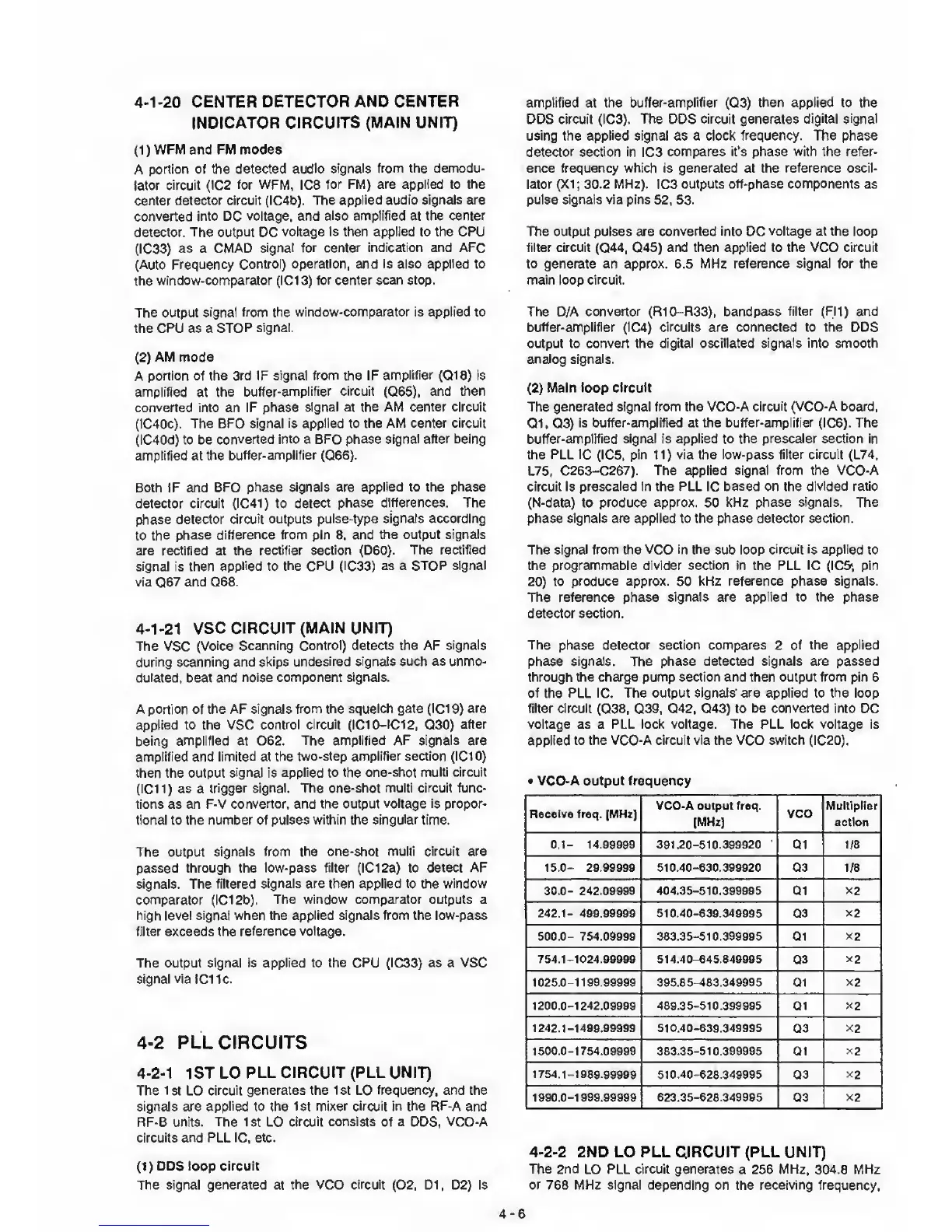
•
VCO-A output frequency
Receive freq.
[MHz]
VCO-A output freq.
[MHz]
VCO
Multiplier
action
0.1-
14.99999
391.20-510.399920
Q1 1/8
1S.0- 29.99999
510.40-630.399920
Q3 1/8
30.0-
242,09999
404.35-510.399995
Q1
X2
242.1- 499.99999
510
40-639.349095
Q3
X2
500.0-
754.09999
383.35-510.399995
Q1
X2
754.1-1024.0909Q 514.40-645.846995
Q3
x2
1025.0-1199.99999
395.85 483.349995 Q1
x2
1200.0-1242.09909 489.35-510.399905
Q1
x2
1242.1-1490.99999 510.40-639.346995
Q3
X2
1500-0-1754.09999 383.35-510.399995
Q1
x2
1754.1-1088.99999 510.40-628.349995
Q3
x2
1090.0-1099.99990
623.35-626.349905
Q3
x2
4-2-2
2ND LO PLL CIRCUIT (PLL UNIT)
The
2nd
LO
PLL circuit generates
a 256 MHz. 304.8 MHz
or
768 MHz
signal
depending on the receiving
frequency.
4-6
 Loading...


