5-1
SECTION 5 ADJUSTMENT PROCEDURE
5-1 PREPARATION
■ REQUIRED EQUIPMENT
EQUIPMENT GRADE AND RANGE EQUIPMENT GRADE AND RANGE
DC power supply
Output voltage: 13.8 V DC
Current capacity: At least 2 A
Standard signal
generator (SSG)
Frequency range: 0.1~3000 MHz
Output level: 0.1 μV to 32 mV
(−127~−17 dBm)
Output impedance
: 50 Ω
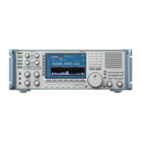
Short plug
Modified 3.5 mm (⅛˝) monaural plug
(See the illustration below)
■ ENTERING THE ADJUSTMENT MODE
1. Connect the JIG cable (see the illustration below) to the
[REMOTE] jack.
Short circuited
[JIG cable]
3-conductor 3.5(d) mm plug
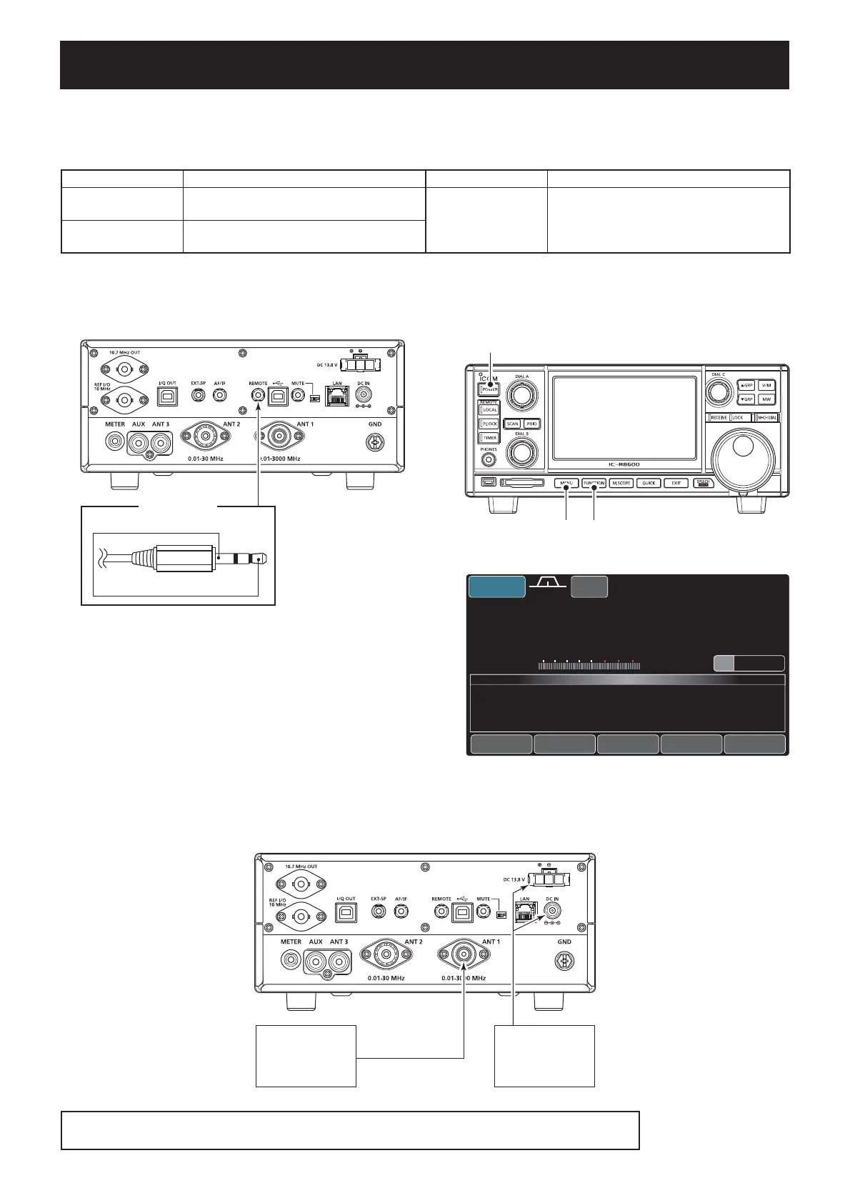
2. While holding down both [MENU] and [FUNCTION], turn
the power ON.
[FUNCTION][MENU]
[POWER]
3. The adjustment main menu is displayed as below.
14.150.00
0
00
ANT1
VFO
12:00
USB
FIL2
AGC-F
S
(
/'
W'
C
&522$(
&52&
(2)#
&8&52
13579
+20 +40 +60dB
FRONT
PRESET
REF
HF-RX
VU-RX
TS
00
20k
ADJUST MODE
Z
■ CONNECTIONS
Standard signal
generator (SSG)
0.1~3000 MHz
0.1μV to 32 mV
DC Power supply
- 13.8 V DC/≥3 A
- AD-55NS
- SP-39AD
The tests described in this section should be measured and adjusted with the above test equipment.
However, a radio tester can also be used for these adjustment procedures.

 Loading...