4 - 4
4-4 CPU PORT ALLOCATION
Pin
No.
LINE
NAME
DESCRIPTION I/O
1 PWRSW
[POWER ] input.
L=Pushed.
I
2–5 KS3–KS0
Key matrix.
O
6–9 KR3–KR0 I
12 CSHIFT
CPU clock frequency shift.
H=Clock frequency is shifted.
O
15 PCON
Main power supply line “VCC” control.
H=The transceiver's power is ON.
O
16 LIGHT
LED backlight control.
L=The backlight is ON.
O
17 CHGC
Charger circuit control.
H=While charging.
O
18 VOLCK D/A converter serial clock. O
19 VOLDA D/A converter serial data. O
27 UNLOCK
PLL unlock detection.
H=The PLL is unlocked.
I
28 EXTPTT
External [PTT] input.
H=Pushed.
I
37 INTPTT
Internal [PTT] input.
L=Pushed.
I
38 ESIO EEPROM serial data. I/O
39 ECK EEPROM serial clock. O
40 PLLDATA PLL IC serial data. O
41 PLLCK PLL IC serial clock. O
42 PLLSTB PLL IC strobe. O
43 PPS
PLL IC power saving mode control.
H=Power saving mode.
O
44 DACLK D/A converter serial clock. O
45 DADI D/A converter serial data. O
46 DALD D/A converter strobe. O
47 R5C
RX power supply line “R5” control.
L=During receive.
O
48 T5C
TX power supply line “T5” control.
H=During transmit.
O
49 IOSTB Expander strobe. O
50 IOEN
Expander chip enable.
H=Output enable.
O
51 PS5C
Power supply line “PS5” control.
L= The transceiver's power is ON and
in the power saving mode.
O
52 INTMIC
MIC line switch (Q7) control.
H=Internal MIC is used.
O
53 PLL SW
PLL IC loop fi lter switching.
L= The PLL lockup time is set to short.
O
Pin
No.
LINE
NAME
DESCRIPTION I/O
54 DETMUTE
RX AF line switch (IC904) control.
L=AF mute (The quelch is closed).
O
56 TXMUTE
Transmission mute.
L=TX mute.
O
57 MMUTE
MIC mute switch (IC909) control.
L= While DTMF or 1750 Hz tone is
transmitted.
O
58 SQLSW
Noise fi lter select.
L= The narrow FM mode is selected.
O
98 CTCSS Outputs CTCSS/DTCS signals. O
99 DTMF
• During transmit, outputs DTMF/
1750 Hz tone signals.
• During receive, outputs beep sounds
(Square waves)
O
104 VOX Microphone input sensing voltage. I
105 BTVIN Battery voltage. I
106 VIN External power source voltage. I
107 BTSENC Battery type detection. I
108 RXTEMP
Temperature sensing voltage. (For
Receiving)
I
109 TXTEMP
Temperature sensing voltage. (For
Transmitting)
I
110 REMOTE
External equipment connection
detection.
I
111 RTONE* Weather alert signal decoding input. I
112 CTCIN
Tone signals (CTCSS, DTCS, DTMF
and 1750 Hz tone) decoding input.
113 SD
RSSI voltage from the IF demodulator
IC (IC313).
I
114 TXI-V TX current sensing voltage. I
115 AFSTBY
AF power AMP control.
H=AF power AMP (IC1) is activated.
O
116 DIUD2 [DIAL] input. (phase A) I
117 NOISE Noise level detection. I
118 DICK2 [DIAL] input. (phase B) I
119 BTDET
Battery pack attachment detection.
L= The battery pack (BP-264, BP-265)
is attached.
I
120 DCIN
External power source connectinon
detection.
L= An external power source is connected.
I
121 DIUD [VOL] input. (phase A) I
122 DICK [VOL] input. (phase B) I
125 KS4 Key matrix. O
*; Only for the U.S.A. version transceiver.
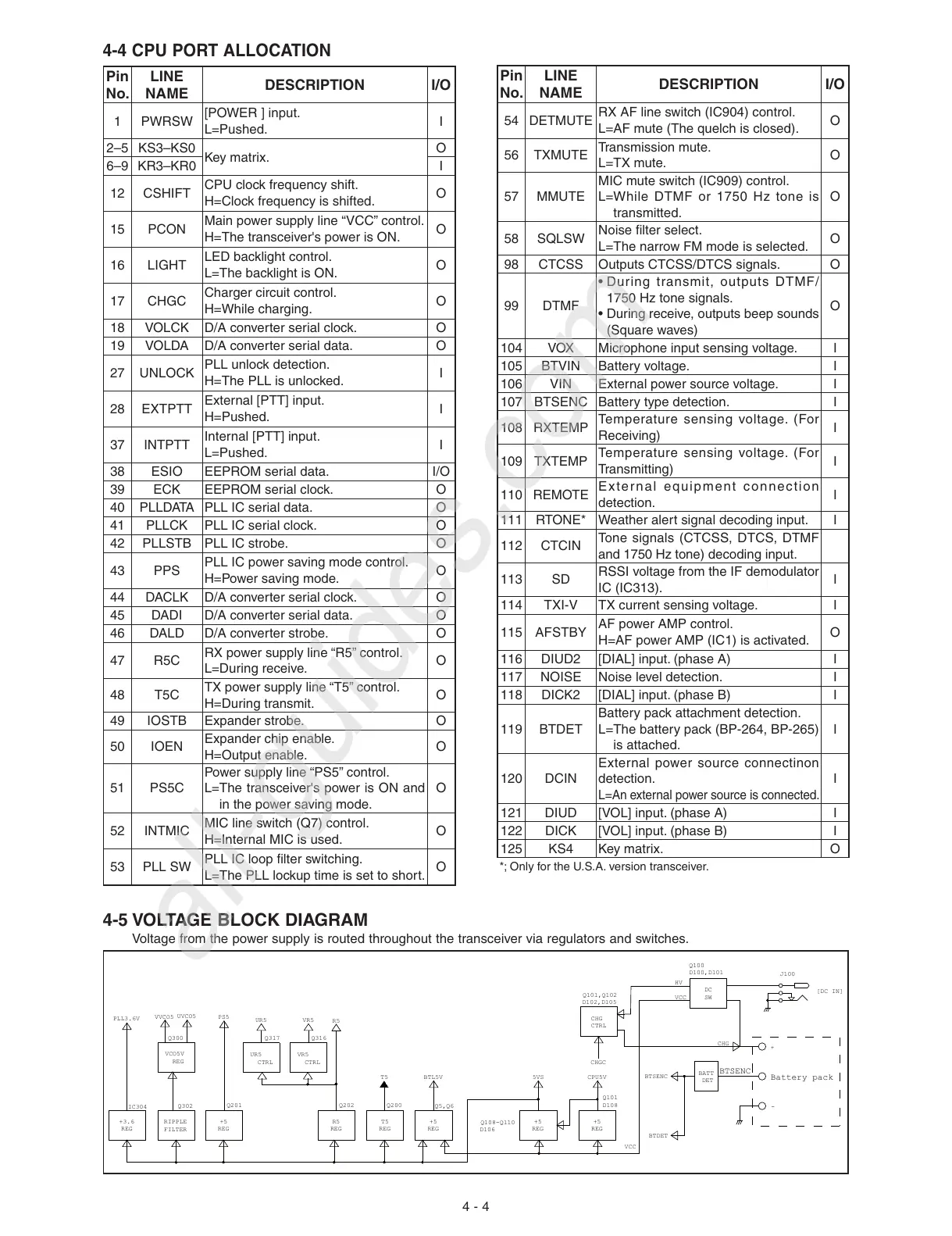
4-5 VOLTAGE BLOCK DIAGRAM
Voltage from the power supply is routed throughout the transceiver via regulators and switches.
J100
[DC IN]
+5
REG
+5
REG
+5
REG
+5
REG
DC
SW
BTSENC
Battery pack
HV
VCC
VCO5V
REG
VVCO5
Q300
+
-
Q100
D100,D101
CHG
D102,D105
Q101,Q102
CHG
CHGC
DET
BATT
VCC
CPU5V
5VS
T5
T5
REG
REG
R5
R5
CTRL
VR5
VR5
UR5
UR5
CTRL
PS5
BTL5V
BTSENC
PLL3.6V
+3.6
REG
IC304
Q316
Q317
D106
Q108-Q110
Q101
Q5,Q6
FILTER
RIPPLE
Q302
Q201
Q202
Q200
D108
CTRL
BTDET
UVCO5
 Loading...


