4 - 2
• 2ND IF CIRCUITS
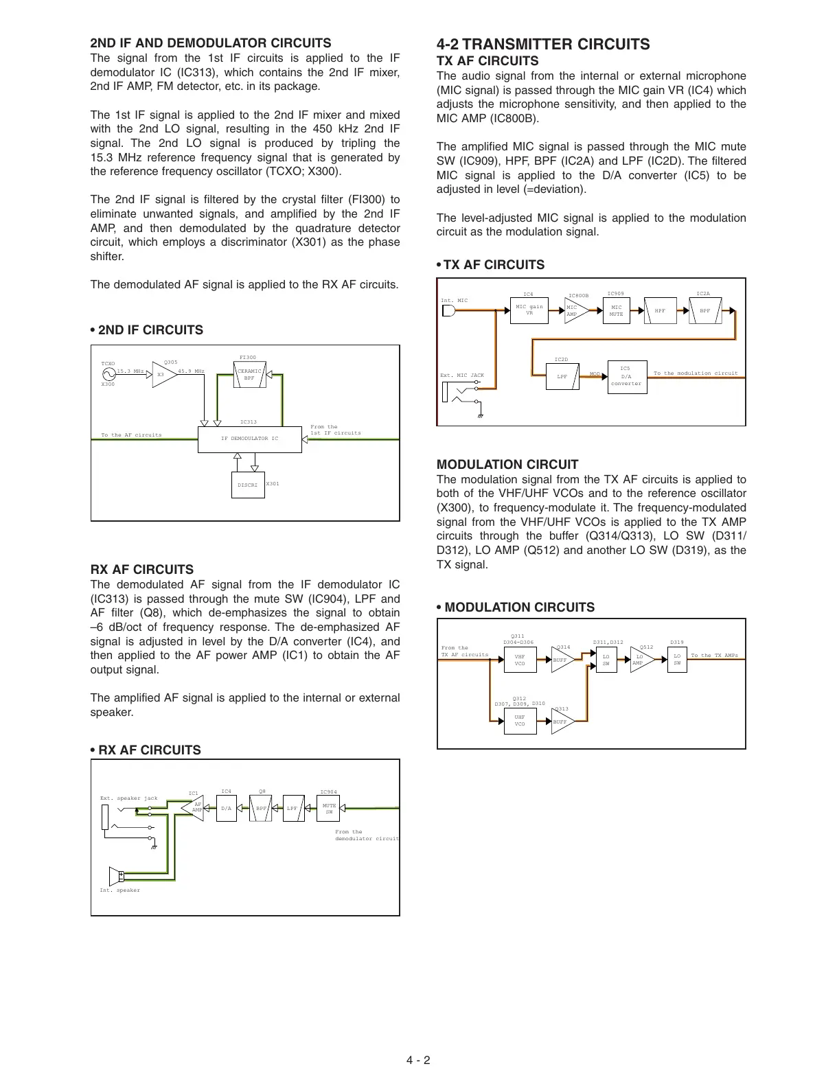
• RX AF CIRCUITS
BPF
CERAMIC
IF DEMODULATOR IC
DISCRI
FI300
IC313
X301
TCXO
X300
15.3 MHz 45.9 MHz
Q305
From the
1st IF circuits
To the AF circuits
X3
Ext. speaker jack
Int. speaker
AF
AMP
LPFD/A BPF
SW
MUTE
From the
demodulator circuit
IC4
IC1
Q8
IC904
2ND IF AND DEMODULATOR CIRCUITS
The signal from the 1st IF circuits is applied to the IF
demodulator IC (IC313), which contains the 2nd IF mixer,
2nd IF AMP, FM detector, etc. in its package.
The 1st IF signal is applied to the 2nd IF mixer and mixed
with the 2nd LO signal, resulting in the 450 kHz 2nd IF
signal. The 2nd LO signal is produced by tripling the
15.3 MHz reference frequency signal that is generated by
the reference frequency oscillator (TCXO; X300).
The 2nd IF signal is filtered by the crystal filter (FI300) to
eliminate unwanted signals, and amplified by the 2nd IF
AMP, and then demodulated by the quadrature detector
circuit, which employs a discriminator (X301) as the phase
shifter.
The demodulated AF signal is applied to the RX AF circuits.
RX AF CIRCUITS
The demodulated AF signal from the IF demodulator IC
(IC313) is passed through the mute SW (IC904), LPF and
AF filter (Q8), which de-emphasizes the signal to obtain
–6 dB/oct of frequency response. The de-emphasized AF
signal is adjusted in level by the D/A converter (IC4), and
then applied to the AF power AMP (IC1) to obtain the AF
output signal.
The amplified AF signal is applied to the internal or external
speaker.
4-2 TRANSMITTER CIRCUITS
TX AF CIRCUITS
The audio signal from the internal or external microphone
(MIC signal) is passed through the MIC gain VR (IC4) which
adjusts the microphone sensitivity, and then applied to the
MIC AMP (IC800B).
The amplified MIC signal is passed through the MIC mute
SW (IC909), HPF, BPF (IC2A) and LPF (IC2D). The filtered
MIC signal is applied to the D/A converter (IC5) to be
adjusted in level (=deviation).
The level-adjusted MIC signal is applied to the modulation
circuit as the modulation signal.
Int. MIC
Ext. MIC JACK
HPF
LPF
BPF
MIC
MUTE
MIC
AMP
To the modulation circuit
MOD
IC5
IC2D
IC2A
D/A
converter
MIC gain
VR
IC909
IC800B
IC4
BUFF
UHF
VCO
BUFF
LO
AMP
VHF
VCO
From the
TX AF circuits
To the TX AMPs
Q512
D304-D306
Q311
Q314
Q313
D310
D309,
D307,
Q312
D311,D312
D319
LO
SW
LO
SW
• TX AF CIRCUITS
MODULATION CIRCUIT
The modulation signal from the TX AF circuits is applied to
both of the VHF/UHF VCOs and to the reference oscillator
(X300), to frequency-modulate it. The frequency-modulated
signal from the VHF/UHF VCOs is applied to the TX AMP
circuits through the buffer (Q314/Q313), LO SW (D311/
D312), LO AMP (Q512) and another LO SW (D319), as the
TX signal.
• MODULATION CIRCUITS
 Loading...


