RF circuits
VHF 1st mixer
UHF 1st mixer
Q318
46.35MHz
To the
2nd IF circuits
LIMIT
FI301
D313
4-1 RECEIVER CIRCUITS
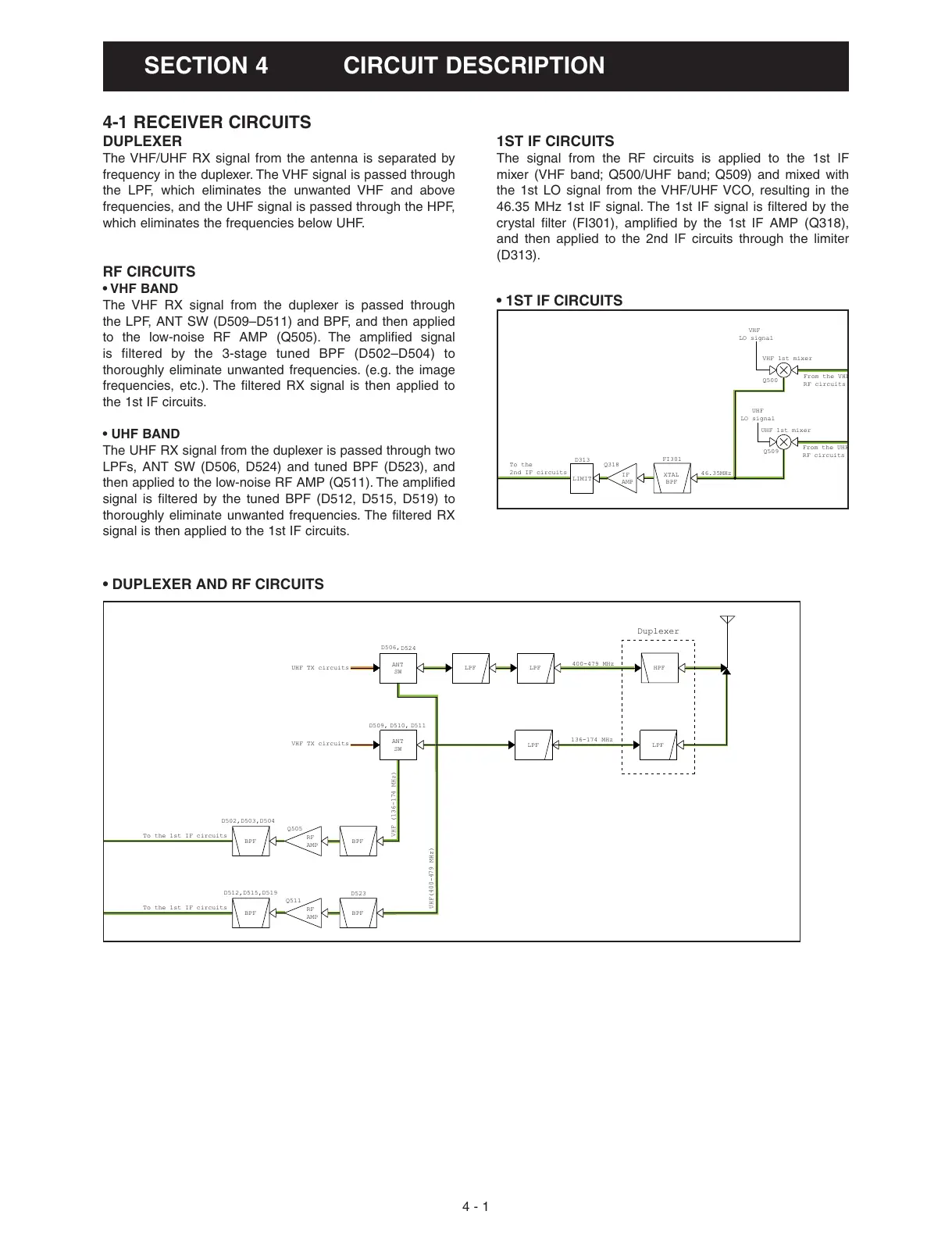
DUPLEXER
The VHF/UHF RX signal from the antenna is separated by
frequency in the duplexer. The VHF signal is passed through
the LPF, which eliminates the unwanted VHF and above
frequencies, and the UHF signal is passed through the HPF,
which eliminates the frequencies below UHF.
RF CIRCUITS
• VHF BAND
The VHF RX signal from the duplexer is passed through
the LPF, ANT SW (D509–D511) and BPF, and then applied
to the low-noise RF AMP (Q505). The amplified signal
is filtered by the 3-stage tuned BPF (D502–D504) to
thoroughly eliminate unwanted frequencies. (e.g. the image
frequencies, etc.). The filtered RX signal is then applied to
the 1st IF circuits.
• UHF BAND
The UHF RX signal from the duplexer is passed through two
LPFs, ANT SW (D506, D524) and tuned BPF (D523), and
then applied to the low-noise RF AMP (Q511). The amplified
signal is filtered by the tuned BPF (D512, D515, D519) to
thoroughly eliminate unwanted frequencies. The filtered RX
signal is then applied to the 1st IF circuits.
1ST IF CIRCUITS
The signal from the RF circuits is applied to the 1st IF
mixer (VHF band; Q500/UHF band; Q509) and mixed with
the 1st LO signal from the VHF/UHF VCO, resulting in the
46.35 MHz 1st IF signal. The 1st IF signal is filtered by the
crystal filter (FI301), amplified by the 1st IF AMP (Q318),
and then applied to the 2nd IF circuits through the limiter
(D313).
 Loading...


