5 - 11
ADJUSTMENT
TRANSCEIVER’S
CONDITION
OPERATION
ADJUSTMENT
ITEM
VALUE
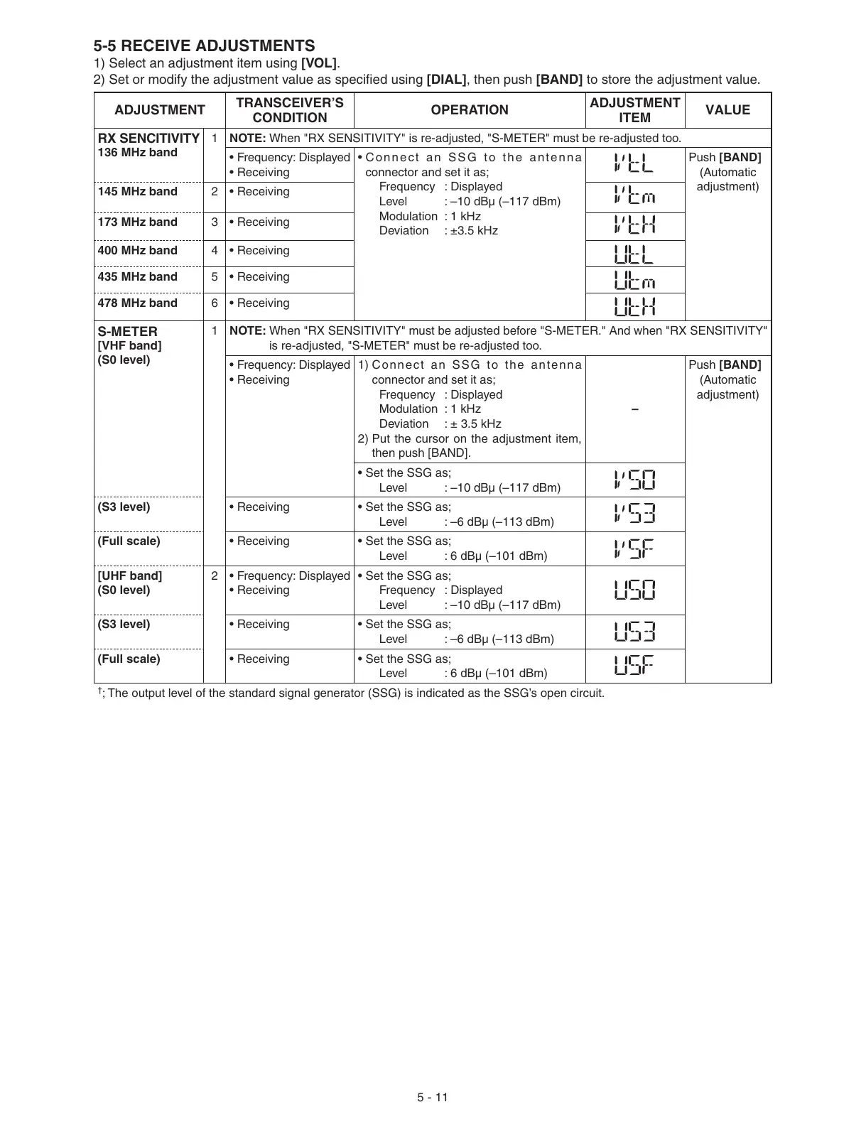
RX SENCITIVITY
136 MHz band
1 NOTE: When "RX SENSITIVITY" is re-adjusted, "S-METER" must be re-adjusted too.
• Frequency: Displayed
• Receiving
• Connect an SSG to the antenna
connector and set it as;
Frequency : Displayed
Level : –10 dBμ (–117 dBm)
Modulation : 1 kHz
Deviation : ±3.5 kHz
Push [BAND]
(Automatic
adjustment)
145 MHz band 2 • Receiving
173 MHz band 3 • Receiving
400 MHz band 4 • Receiving
435 MHz band 5 • Receiving
478 MHz band 6 • Receiving
S-METER
[VHF band]
(S0 level)
1 NOTE: When "RX SENSITIVITY" must be adjusted before "S-METER." And when "RX SENSITIVITY"
is re-adjusted, "S-METER" must be re-adjusted too.
• Frequency: Displayed
• Receiving
1) Connect an SSG to the antenna
connector and set it as;
Frequency : Displayed
Modulation : 1 kHz
Deviation : ± 3.5 kHz
2) Put the cursor on the adjustment item,
then push [BAND].
–
Push [BAND]
(Automatic
adjustment)
• Set the SSG as;
Level : –10 dBμ (–117 dBm)
(S3 level) • Receiving • Set the SSG as;
Level : –6 dBμ (–113 dBm)
(Full scale) • Receiving • Set the SSG as;
Level : 6 dBμ (–101 dBm)
[UHF band]
(S0 level)
2• Frequency: Displayed
• Receiving
• Set the SSG as;
Frequency : Displayed
Level : –10 dBμ (–117 dBm)
(S3 level) • Receiving • Set the SSG as;
Level : –6 dBμ (–113 dBm)
(Full scale) • Receiving • Set the SSG as;
Level : 6 dBμ (–101 dBm)
†
; The output level of the standard signal generator (SSG) is indicated as the SSG’s open circuit.
5-5 RECEIVE ADJUSTMENTS
1) Select an adjustment item using [VOL].
2) Set or modify the adjustment value as specifi ed using [DIAL], then push [BAND] to store the adjustment value.
 Loading...


