5 - 3
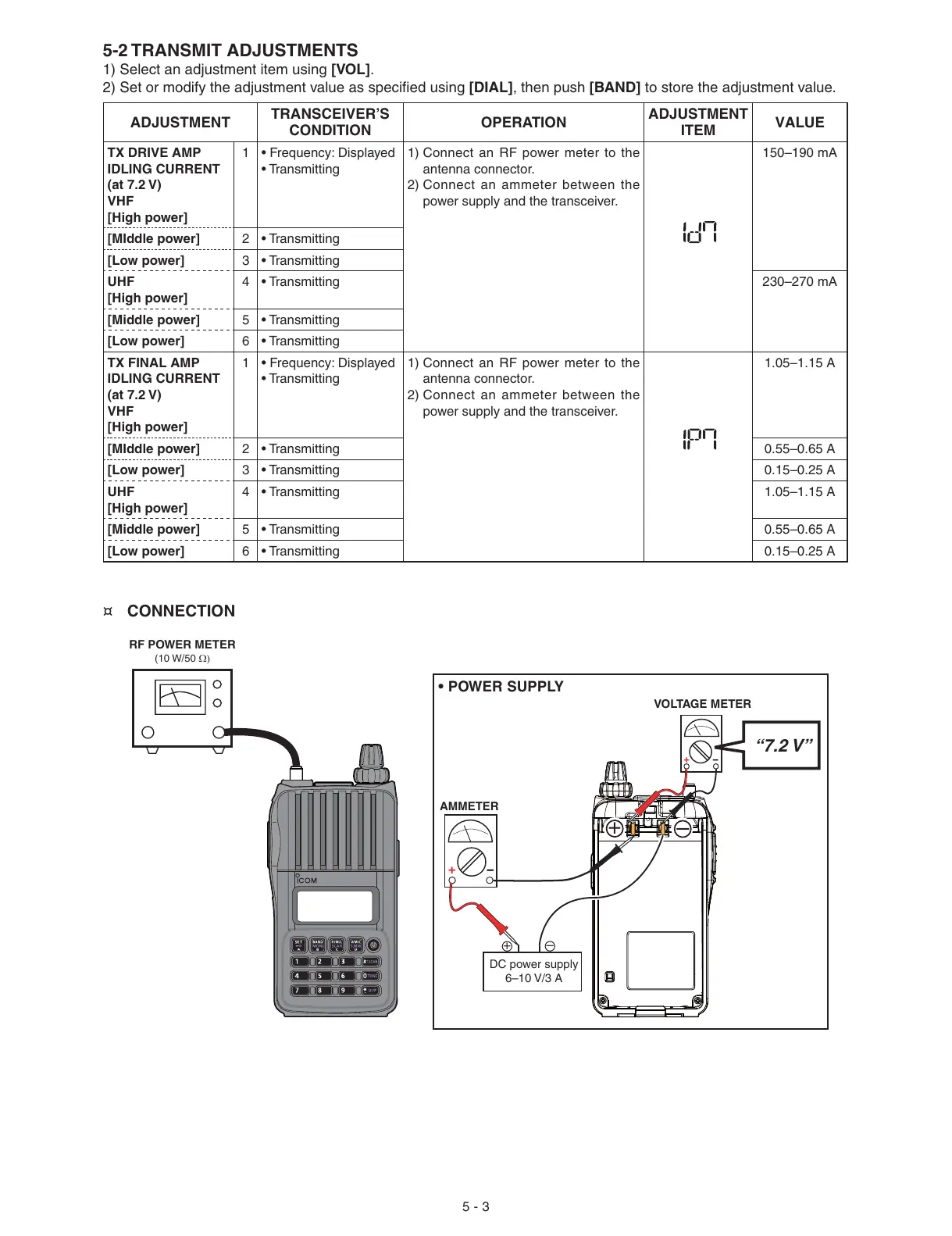
¤ CONNECTION
• POWER SUPPLY
ADJUSTMENT
TRANSCEIVER’S
CONDITION
OPERATION
ADJUSTMENT
ITEM
VALUE
TX DRIVE AMP
IDLING CURRENT
(at 7.2 V)
VHF
[High power]
1 • Frequency: Displayed
• Transmitting
1) Connect an RF power meter to the
antenna connector.
2) Connect an ammeter between the
power supply and the transceiver.
150–190 mA
[MIddle power] 2 • Transmitting
[Low power] 3 • Transmitting
UHF
[High power]
4 • Transmitting 230–270 mA
[Middle power] 5 • Transmitting
[Low power] 6 • Transmitting
TX FINAL AMP
IDLING CURRENT
(at 7.2 V)
VHF
[High power]
1 • Frequency: Displayed
• Transmitting
1) Connect an RF power meter to the
antenna connector.
2) Connect an ammeter between the
power supply and the transceiver.
1.05–1.15 A
[MIddle power] 2 • Transmitting 0.55–0.65 A
[Low power] 3 • Transmitting 0.15–0.25 A
UHF
[High power]
4 • Transmitting 1.05–1.15 A
[Middle power] 5 • Transmitting 0.55–0.65 A
[Low power] 6 • Transmitting 0.15–0.25 A
5-2 TRANSMIT ADJUSTMENTS
1) Select an adjustment item using [VOL].
2) Set or modify the adjustment value as specifi ed using [DIAL], then push [BAND] to store the adjustment value.
AMMETER
+
−
DC power supply
6–10 V/3 A
+
–
“7.2 V”
VOLTAGE METER
+
−
+
–
RF POWER METER
(10 W/50 Ω)

 Loading...


