5 - 9
ADJUSTMENT
TRANSCEIVER’S
CONDITION
OPERATION
ADJUST-
MENT
ITEM
VALUE
FM (Narrow)
DEVIATION
VHF (Low band)
1 • Frequency: Displayed
• Transmitting
1) Connect a modulation analyzer to
the antenna connector through an
attenuator, and set it as;
HPF : OFF
LPF : 20 kHz
2) Connect an audio generator to the JIG
cable #2 and set it as;
Frequency : 1 kHz
Level : 150 mVrms
±2.0 to ±2.2
kHz
VHF (High band) 2 • Frequency: Displayed
• Transmitting
UHF ( Low band) 3 • Frequency: Displayed
• Transmitting
UHF (High band) 4 • Frequency: Displayed
• Transmitting
VHF (Low band) 5 • Frequency: Displayed
• Transmitting
• Set the audio generator as;
Level : OFF
Minimum level
VHF (High band) 6 • Frequency: Displayed
• Transmitting
UHF ( Low band) 7 • Frequency: Displayed
• Transmitting
UHF (High band) 8 • Frequency: Displayed
• Transmitting
5-4 MODURATION ADJUSTMENTS (Continued)
1) Select an adjustment item using [VOL].
2) Set or modify the adjustment value as specifi ed using [DIAL], then push [BAND] to store the adjustment value.
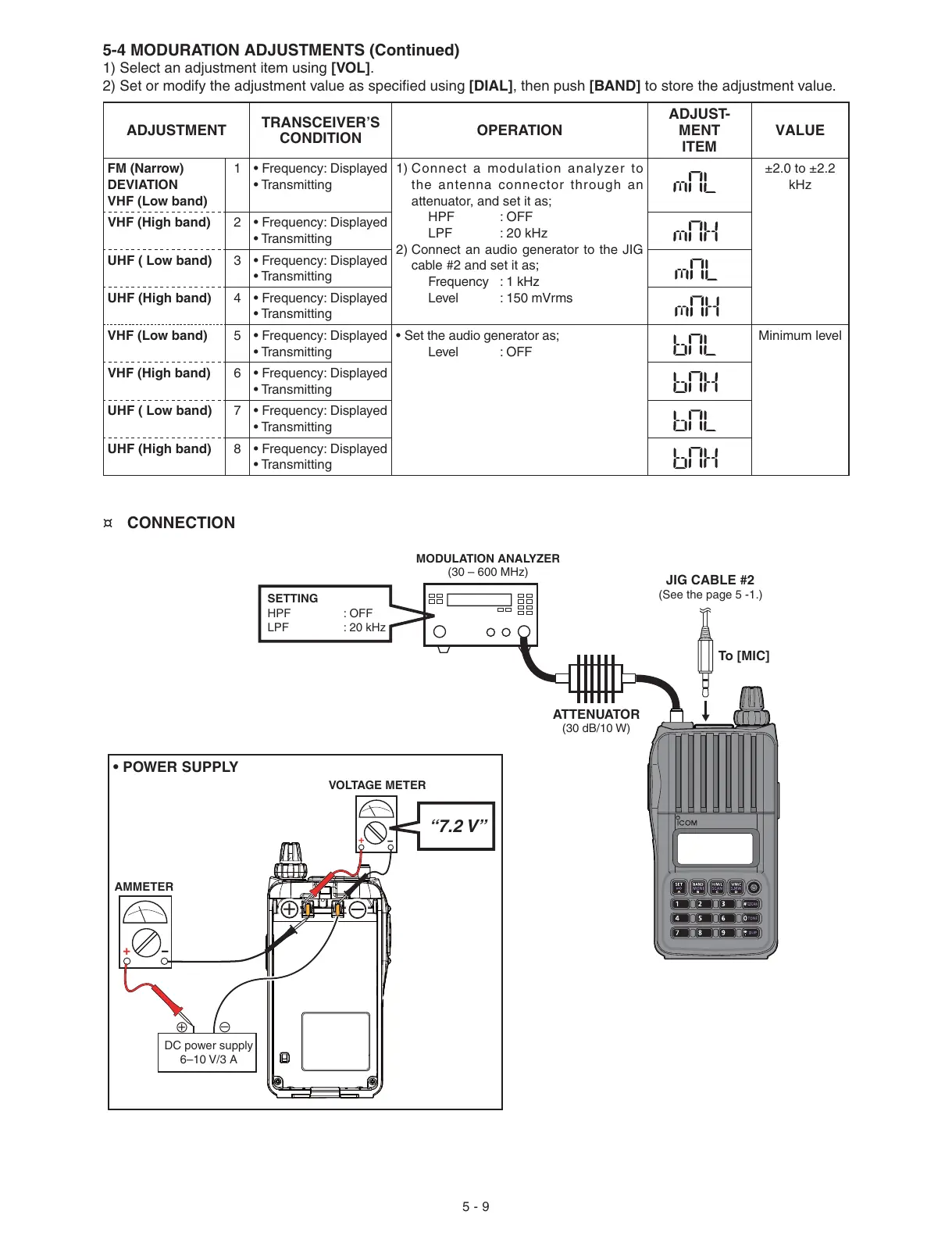
¤ CONNECTION
MODULATION ANALYZER
(30 – 600 MHz)
SETTING
HPF : OFF
LPF : 20 kHz
ATTENUATOR
(30 dB/10 W)
(See the page 5 -1.)
JIG CABLE #2
To [MIC]
• POWER SUPPLY
AMMETER
+
−
DC power supply
6–10 V/3 A
+
–
“7.2 V”
VOLTAGE METER
+
−
+
–
 Loading...


