Do you have a question about the Icom IC-V200 and is the answer not in the manual?
Contact information for support and service.
Guidelines for ordering parts efficiently.
Safety precautions and operating guidelines for repair.
Details general, receiver, and transmitter performance parameters.
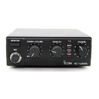
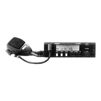
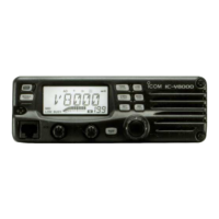
Describes front and rear panel controls, indicators, and connections.
Identifies key components on the internal main and logic unit boards.
Provides a high-level overview of the unit's functional circuit blocks.
Describes antenna, RF, and IF receiver circuits.
Explains audio, squelch, and CTCSS signal paths and functions.
Explains transmitter stages, PLL frequency synthesis, and logic control circuits.
Covers front panel indicator functions.
Illustrates and lists various mechanical components.
Shows assembly diagrams for main, front, and logic unit connectors.
Details adjustment procedures for PLL, transmitter, receiver, and CTCSS circuits.
Shows component placement diagrams for the main and logic units.
Shows component placement diagrams for the CTCSS and front units.
Provides comprehensive parts lists for EF, Front, Main, Logic, and CTCSS units.
Details layouts, circuit diagrams, and parts lists for UT-32 and UT-33 optional units.
Provides detailed voltage and circuit diagrams for CTCSS, Front, Logic, and Main units.
| Frequency Range | 136-174 MHz |
|---|---|
| Modulation | FM |
| Power Supply | 13.8V DC |
| Antenna Impedance | 50 ohms |
| Voltage | 13.8V |
| Dimensions | 120 x 140 x 40 mm |